Continue to Site

Welcome to EDAboard.com

Welcome to our site! EDAboard.com is an international Electronics Discussion Forum focused on EDA software, circuits, schematics, books, theory, papers, asic, pld, 8051, DSP, Network, RF, Analog Design, PCB, Service Manuals... and a whole lot more! To participate you need to register. Registration is free. Click here to register now.

Capacitors with regards to A/C and D/C

Status
Not open for further replies.

Music Manic

Junior Member level 2
Joined
Aug 30, 2012
Messages
21
Helped
1
Reputation
2
Reaction score
1
Trophy points
1,283
Activity points
1,481
Hi,

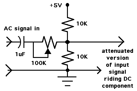
How does a circuit separate the audio signal (which is A/C) from the D/C circuit?

When a circuit is closed and the voltage is applied everything in that circuit is D/C right!
So when an A/C signal, such as from a microphone or guitar pickup enters the circuit, how does the D/C circuit "translate" the fluctuating -ve to +ve signal into D/C?

I know that the capacitors are charged by the D/C voltage but how does A/C interact?

Thanks
 

Capacitors and Inductors (coils) have a behaviour which is heavily dependant on the frequency (fluctuations) of the signals at their two ends.

Take a capacitor (for example). If a fixed (non-fluctuating) DC voltage is applied, then after a while there will be NO current flow. However if the voltage "fluctuates" then some current WILL flow, and how much flows depends on how fast the fluctuations are. Higher frequency means more current will flow -- equivalent to a fall in resistance.

And inductor behaves pretty much exactly opposite to this. I.e. at DC and after waiting a while, the Inductor will look like a short. But as the frequency increases, the current drops -- equivalent to increase in resistance.

There are other aspects to this as well.... but thats the basics. And clever electronics type folks make good use of these properties.

cheers!
 

DC voltage is used to fix the operating range of the circuit just like the amplifiers Q point

whereas the AC signal from the other source gives the ip signal which is to be amplified by the design

now the role cap in the case of DC is similar to open circuit due to INFINITE REACTANCE to the supply voltage
in AC based on the frequency their role will vary that is why we have three bands in analysis of any circuit low mid and high
 

When you have both d.c. and a.c. present at any point in a circuit the result is the algebraic sum of both.

Draw a graph of d.c. vs time and you will have a straight line above (or below, depending on polarity) the zero line by a distance which is proportional to the value of the voltage.

Draw a graph of d.c. plus an a.c. signal and you have a wavy line above (or below) the zero line.

Although it is one line it is, nevertheless, the sum of two components, the d.c. one and the a.c. one.

The d.c. doesn't pass through a capacitor. The a.c. does.
 
the effective resultant is the super position of both the AC AND DC supply response of any circuit or component
 

how does the D/C circuit "translate" the fluctuating -ve to +ve signal into D/C?

A simple resistor network can lift an AC signal up into the DC region. It is frequently done at the inputs of amplifying devices such as transistors and op amps.

Schematic:

1_1347184420.png


I have a Youtube video showing capacitor behavior with AC and DC waveforms.

It consists of animated simulations, which portray current flowing through wires, and the capacitors charging and discharging.

www.youtube.com/watch?v=eIWEU4pObJw
 

When you have both d.c. and a.c. present at any point in a circuit the result is the algebraic sum of both.

Draw a graph of d.c. vs time and you will have a straight line above (or below, depending on polarity) the zero line by a distance which is proportional to the value of the voltage.

Draw a graph of d.c. plus an a.c. signal and you have a wavy line above (or below) the zero line.

Although it is one line it is, nevertheless, the sum of two components, the d.c. one and the a.c. one.

The d.c. doesn't pass through a capacitor. The a.c. does.

One sentence can make the penny drop! Now I can see how A.C is "translated".
This means that the D.C voltage must create a "zero" point so that the +ve and -ve voltage of the A.C can reach it's peaks without clipping right?
Does this mean that the D.C voltage has to be "calibrated" in a certain way? I mean, if a capacitor is receiving the 9 volts from a 9 volt battery and an A.C voltage adds to that it will add and decrease the charge to capacitors plates will it not?

Is this also why part of a transistor works at half the supply voltage, to create the -ve to +ve peak to peak?

Thanks
 

This means that the D.C voltage must create a "zero" point so that the +ve and -ve voltage of the A.C can reach it's peaks without clipping right?

The d.c. point, for example at the collector of a transistor, effectively becomes the zero point for the a.c. signal.

Does this mean that the D.C voltage has to be "calibrated" in a certain way? I mean, if a capacitor is receiving the 9 volts from a 9 volt battery and an A.C voltage adds to that it will add and decrease the charge to capacitors plates will it not?

If one plate of capacitor is at a rail (supply) voltage there won't be any (there SHOULDN'T be any) a.c./signal voltage there. For signal analysis, all supply lines, whether they are pos, neg or zero volts are all considered to be shorted together, i.e. there is zero impedance between any of them - they are considered to be ideal voltage sources.

Is this also why part of a transistor works at half the supply voltage, to create the -ve to +ve peak to peak?

Yes, more or less. The collector will sit at around half the supply voltage so that it may increase or decrease symetrically without clipping.

dcgraph.gif


acgraph.gif


dcplusacgraph.gif
 
If one plate of capacitor is at a rail (supply) voltage there won't be any (there SHOULDN'T be any) a.c./signal voltage there. For signal analysis, all supply lines, whether they are pos, neg or zero volts are all considered to be shorted together, i.e. there is zero impedance between any of them - they are considered to be ideal voltage sources.

Ahh!! This is getting even more clearer. So, a pickup coil from a guitar pickup has both ends shorted/joined so that send their current down the tip of the guitar lead? The ground of the lead is used as the reference for voltage. This ground has no charge?

Thank you Sir.
 

My comments regarding all supply lines being connected together applies to signal analysis of an amplifier.

A guitar's pickup is a generator. Its ends are not connected together. Current flows through the coil and the two wires. The two wires are usually in the form of a single cored screened lead, so the current flows in both the centre conductor and the screen. The fact that the screen is usually connected to Earth or "ground" is irrelevant.
 

Status
Not open for further replies.

Part and Inventory Search

Welcome to EDABoard.com

Sponsor

Back
Top