Continue to Site

Welcome to EDAboard.com

Welcome to our site! EDAboard.com is an international Electronics Discussion Forum focused on EDA software, circuits, schematics, books, theory, papers, asic, pld, 8051, DSP, Network, RF, Analog Design, PCB, Service Manuals... and a whole lot more! To participate you need to register. Registration is free. Click here to register now.

the problem with the preamp

Status
Not open for further replies.

ql396387901

Newbie level 2
Joined
Apr 25, 2012
Messages
2
Helped
0
Reputation
0
Reaction score
0
Trophy points
1,281
Activity points
1,297
hello guys,

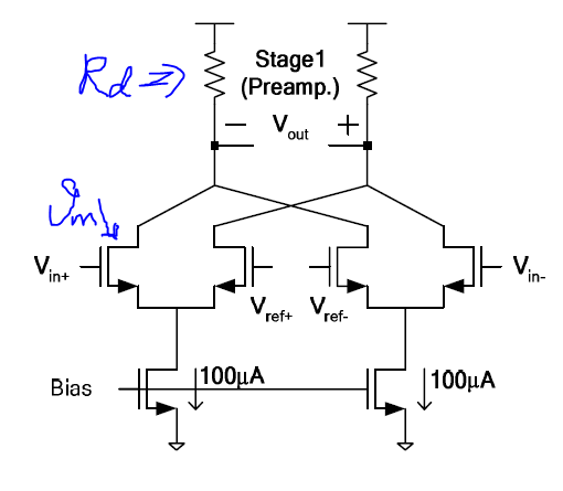
I have a problem with the small signal analysis with the preamp circuit. You can see the circuit in the picture. At the beginning I thought

the gain Av = 2*gm*Rd. But when I do the simulation, the result is difference with my analysis.

can you help me?


https://obrazki.elektroda.pl/85_1346598160.png
 

Are you counting the outputs individually? Or are you bridging across them?

Each output swings within a volt range which is the same swing as the input. This is because mosfets are voltage-controlled devices.

However notice that you can put a load across the outputs, and get 2x the voltage gain.

My simulation shows this amp can serve as a power amp. The topmost resistors can be as low as 10 ohms.
 

At the beginning I thought the gain Av = 2*gm*Rd.
It depends how you define gain.
If Vref1 = Vref2 = constant, and you define gain as: gain = (Vout+ - Vout-) / (Vin+ - Vin-), then gain = Rd*gm, where gm is the value for a single device.

My simulation shows this amp can serve as a power amp. The topmost resistors can be as low as 10 ohms.
With idling currents = 100uA? :-?
 

I wrote: My simulation shows this amp can serve as a power amp. The topmost resistors can be as low as 10 ohms.

With idling currents = 100uA? :-?

The 100 uA bias resulted in the output staying at the upper supply rail.

I found I had to increase the bias to several mA, just to bring the output level to a sensible area of operation.

For a while I tried high values for the upper resistors. However the outputs were mostly a straight line, except at input peaks.

I could not obtain linear response until I made the resistors around 330 ohms.
 

Hi,
if Vref+ and Vref- were tied together, then set them being equal to the common mode voltage of Vin+ and Vin-. the gain of the circut would be 2*gm*Rd, like simple differential pair.
The Cin(Cgs) could be halved at cost of twice power and addtional load cap. I don't think this circut work well as peramp, but it can be a good buffer. because it is difficult to get high gain and low noise.
Ziqi
 
Yes, I tend to agree with Ziqi, because my result (hand calculation) is as follows:

(Vout+)-(Vout-)=-2gm*[(Vin-)-(Vin+)+(Vref+)-(Vref-)].
 

Status
Not open for further replies.

Part and Inventory Search

Welcome to EDABoard.com

Sponsor

Back
Top