Continue to Site
Follow along with the video below to see how to install our site as a web app on your home screen.
Note: This feature may not be available in some browsers.
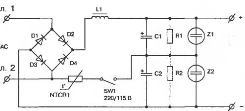
In PC PSU this restriction usually avoid with voltage doubler.It can accept 110V input, but with half output voltage only.
In other words, you wan't to use a different converter topology, e.g. a flyback converter as used in most small and medium power wide range input SMPS.what changes to transformer?. In our country the Grid voltage varies from 80v to 270v during the summers as we have some poor transmission systems so changing the input tape is not the best of option rather this supply should do it in a linear way by adjusting the pwm like we have in offline supplies in the form of laptop and mobile phone chargers etc.
and this, tooHi Also check this. **broken link removed**
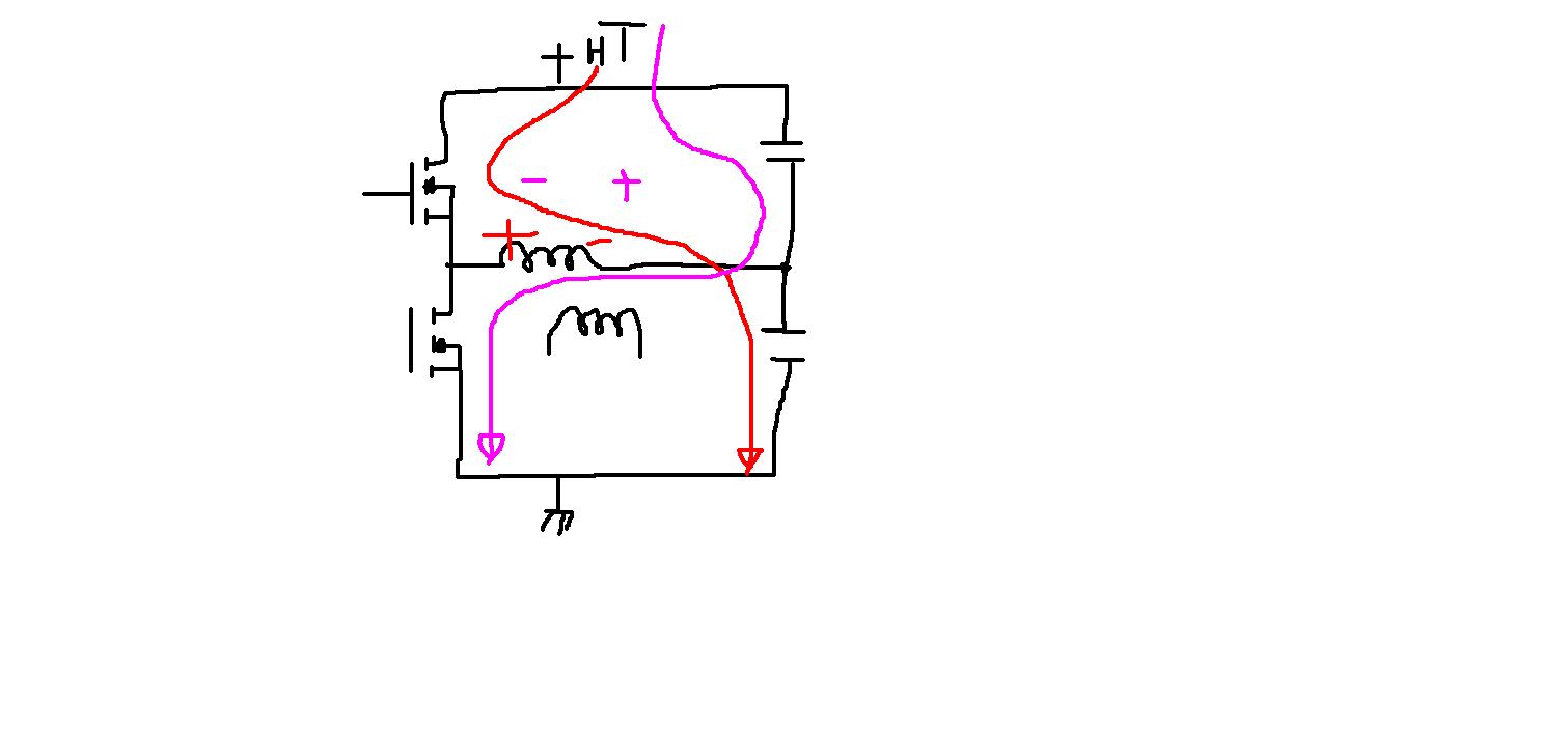
There no snubbers in circuit since all beautifully work without them. However in this scheme it is necessary to understand with feedback on voltage, because in such type possible do not work.
Also, it is necessary to note that TL494 is outdated chip and used mainly by the reason of its small price.
I rather guess this capacitors
I think the circuit operation won't change substantially when omitting the RC combination.
My analysis of the driver RC circuit is as such:
There's no DC current flowing through the resistors.
No, I mean't effectively no DC current through the resistor. The capacitor will no charge up to a noticable voltage, the voltage drop across the RC combination is constantly zero.I think you meant no DC current through capacitor.