Mithun_K_Das
Advanced Member level 3
- Joined
- Apr 24, 2010
- Messages
- 899
- Helped
- 24
- Reputation
- 48
- Reaction score
- 26
- Trophy points
- 1,318
- Location
- Dhaka, Bangladesh, Bangladesh
- Activity points
- 8,254
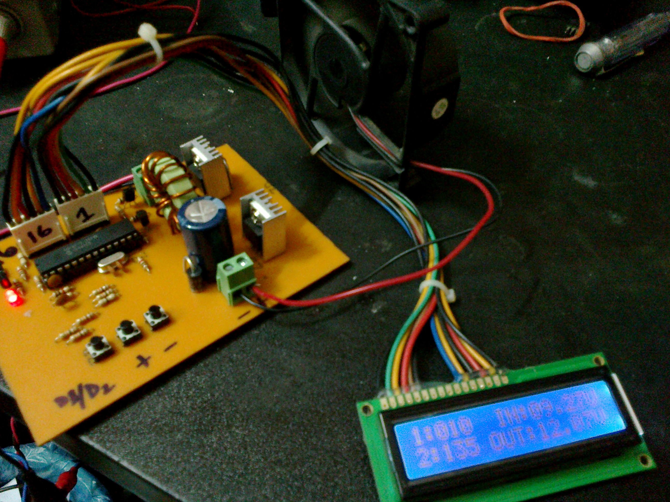
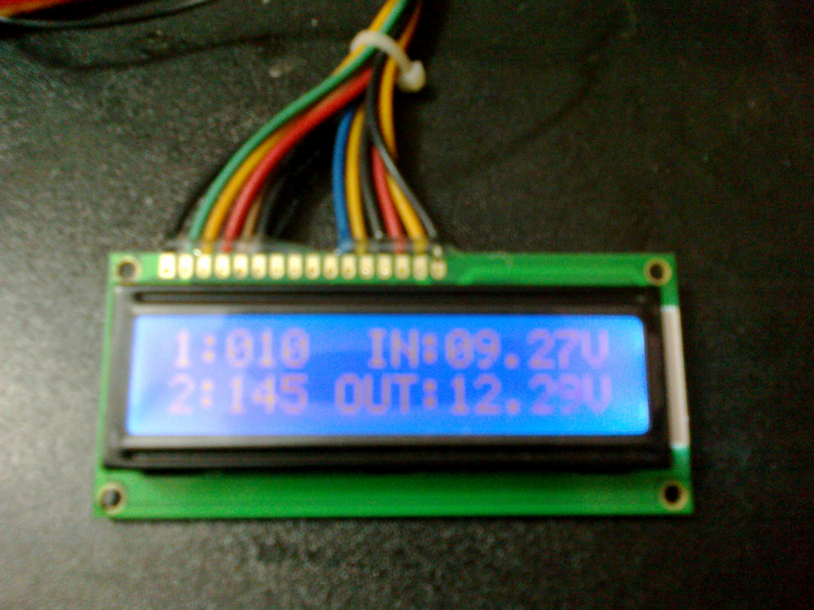
I want to know how to design MPPT solar charge controller. Can anyone help for this case?