Continue to Site

Welcome to EDAboard.com

Welcome to our site! EDAboard.com is an international Electronics Discussion Forum focused on EDA software, circuits, schematics, books, theory, papers, asic, pld, 8051, DSP, Network, RF, Analog Design, PCB, Service Manuals... and a whole lot more! To participate you need to register. Registration is free. Click here to register now.

The problem when wire up in breadboard

Status
Not open for further replies.

john78304

Junior Member level 1
Joined
Apr 18, 2012
Messages
15
Helped
0
Reputation
0
Reaction score
0
Trophy points
1,281
Activity points
1,419
Hi everybody,
In rencent I am doing a project where i have to transmit data 200 metter far from center, therefore i need to convert 232 to 485 RS.I have found a schedule in this
https://www.edaboard.com/threads/246665/#post1058115
https://obrazki.elektroda.pl/77_1334266235.jpg
In this schedule have two parts:
RS232 to rs485 and the other is rs485 to rs232
I have wire up in breadboard and use a computer to stimulate it.TX of com port is attached to TX of max232 of one circuit and output of max232 in other circuit is connected to RX of com port.Two wires A and B of 2 circuits is connected to each other.But when i run it I received data even when the power for circuit is not connected. and when power is connected then it is not work!I have checked it many times but I can see anything wrong in the circuit.Anyone can give me how to check it and have anything go wrong in this circuit ?
this is the code i used:
Code:
#include <cstdlib>
#include <iostream>
#include <windows.h>
#include <stdio.h>
#include <conio.h>
#include <string.h>

#define TIMEOUT_CONSTANT    50
#define ESC                 27


int main(int argc, char* argv[])
{
    char*s="This is a test";
    int          key_pressed   = 0,i=0;
    char         outchar       = 0;
    char         inchar        = 0;
    DWORD        bytes_written = 0;    // Number of bytes written to port
    DWORD        bytes_read    = 0;    // Number of bytes read from port
    COMMTIMEOUTS tempComTimeouts;      // Our temporary time-outs for COM1
    COMMTIMEOUTS savedComTimeouts;     // Stores the original time-outs
    HANDLE       comport       = NULL; // Handle for COM port
    DCB          comSettings;          // Contains various port settings
    char buf[15];

    printf("Sample UART Loopback Terminal Program v1.00.\n");
    printf("COM1 PROGRAM\n\n");
    
    // Open COM port
    if ((comport = 
          CreateFile("COM1", 
                    GENERIC_READ | GENERIC_WRITE,          // for reading and writing
                    0,                                     // exclusive access
                    NULL,                                  // no security attributes
                    OPEN_EXISTING,              
                    FILE_ATTRIBUTE_NORMAL,
                    NULL)) == INVALID_HANDLE_VALUE)
    {
        printf("Unable to open COM1.\n\n");
        printf("Press any key to exit.");
        getch();
        return(1);
    }

    printf("COM1 opened.\n\n");

    // Save time-out parameters for COM1 
    GetCommTimeouts(comport,&savedComTimeouts);
    
    // Set our time-outs 
    tempComTimeouts.ReadIntervalTimeout         = TIMEOUT_CONSTANT;
    tempComTimeouts.ReadTotalTimeoutMultiplier  = TIMEOUT_CONSTANT;
    tempComTimeouts.ReadTotalTimeoutConstant    = TIMEOUT_CONSTANT;
    tempComTimeouts.WriteTotalTimeoutMultiplier = TIMEOUT_CONSTANT;
    tempComTimeouts.WriteTotalTimeoutConstant   = TIMEOUT_CONSTANT;
    SetCommTimeouts(comport,&tempComTimeouts);

    // Set Port parameters.
    // We make a call to GetCommState() first in order to fill
    // the comSettings structure with all the necessary values.
    // Then we change the ones we want and call SetCommState().
    GetCommState(comport, &comSettings);
    comSettings.BaudRate = CBR_9600;
    comSettings.StopBits = ONESTOPBIT;
    comSettings.ByteSize = 8;
    comSettings.Parity   = NOPARITY;
    comSettings.fParity  = FALSE;
    SetCommState(comport, &comSettings);
    
 
     while(1)
     {  
 
          i=0;   
          while(s[i]!=0)                                                     
            {   
                // Send data. if succesful, WriteFile() returns non-zero 
                WriteFile(comport,        // Handle
                          &s[i],      // Outgoing data
                          1,              // Number of bytes to write
                          &bytes_written, // Number of bytes written
                          NULL); i++;
            }
                                                                                   
        // Read data. if succesful, ReadFile() returns non-zero
        ReadFile(comport,                 // Handle
                   buf,                    // Incoming data
                   sizeof(buf),            // Number of bytes to read
                   &bytes_read,           // Number of bytes read
                   NULL); 
                   DWORD j;

        printf("\n%s", buf);
        for(i=0;i<15;i++)
        buf[i]='\0';
 
   }
    // Restore time-out parameters 
    SetCommTimeouts(comport,&savedComTimeouts);
    CloseHandle(comport);
    getch();
    return(0);

}
 

Can you give me the way to check my circuit? I have check all connection is good but i don't know why
when i use ohmmet to measure the resistance between TX and RX of com port, i get the resistance very large, however , when i run my code whithout power for IC it is work!it mean that RX and TX is connected to each other but in fact it is not. when the bettery is connected it is not work.
 

RS485 is differential driver receiver with optional hysteresis.
RS232 is a single-ended unbalanced but bipolar +/-V signal but the threshold is same as TTL or +2x diode drops= 1.3V
Both require a common ground. If my assumption is correct, your ground is not common.
 

RS485 is differential driver receiver with optional hysteresis.
RS232 is a single-ended unbalanced but bipolar +/-V signal but the threshold is same as TTL or +2x diode drops= 1.3V
Both require a common ground. If my assumption is correct, your ground is not common.

Thanks.But in this circuit i let two breadboard very nearly.Do i need two resisrors 120 ohm between A and B of transmission?
and is it correct if i used negative pole of baterry for two breadbroads and GND of ICs?
I also did not use GND of com port.
Could you help me?
 

i would like to see your actuall implementation, just because you need to remember that
the circuit i published and you mentioned is a TTL to TTL communication via max232 ONLY for simulation...
in real life, you have two situations.

PC with RS232 port

and microcontroller with TTL port (direct to the pins) or any board with a max232 (and because that with a rs232 port)

if you have a PC with RS232 port (even a usb serial converter) you ONLY need one MAX232 on the circuit (ommit the one near the Virtual Terminal)
if you have a micro and it's TTL port, you don`t need any max232 at it's side...


also the resistor should be necesary only at longer distances...

don't forget the original **broken link removed**
 
Last edited:
i would like to see your actuall implementation, just because you need to remember that
the circuit i published and you mentioned is a TTL to TTL communication via max232 ONLY for simulation...
in real life, you have two situations.

PC with RS232 port

and microcontroller with TTL port (direct to the pins) or any board with a max232 (and because that with a rs232 port)

if you have a PC with RS232 port (even a usb serial converter) you ONLY need one MAX232 on the circuit (ommit the one near the Virtual Terminal)
if you have a micro and it's TTL port, you don`t need any max232 at it's side...


also the resistor should be necesary only at longer distances...

don't forget the original **broken link removed**
Thanks.In my project I need to communicate between computer(COMM PORT) and micro.But now I want to check 2 circuits that I had wire in breadboard:
-the first breadboard for RS232 to RS485
-the second breadboard for RS485 to RS232
in reality, I need 2 computers to communicate but now have only one therefore I used TX pin of comm port to transmit and also used RX of this port to receive data.
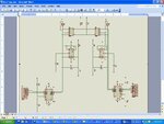
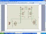
This is the circuit i want to build: converter_1.JPG
And this is the circuit i have used in one computer with only one comm port:
converter_2.JPG
Because I only used on computer thus I had connect TX of comm port to 232 input of one breadboard and RX of comm port to 232 output of the other breardboard.And then I used the program i posted above to transmit and receive data from comm port.But when I am not use 5 Voltage connected to ICs and I supprised due to is read from comm port is exact but when power is connected then it is not work.At first I think that it receiced data may be TX and RX is connected to each other but when i used ohm meter to measure the resistance between TX and RX, i received the value is very large and this mean it is not connected.I am confused why it is not connected but i can received data and when power is connnected it is not work.
I have checked all connected in breadboard, all of them are good.Would you give me how to solved it,i have wire up the circuit in breadboard many times but all are the same.Finally I can not to transmit between two computer.Will i need add something in this circuit in reality?Are there anything wrong in my schematic?:???::???::???:
 

Attachments

  • converter_1.zip
    82.1 KB · Views: 60
  • converter2.zip
    76.1 KB · Views: 50

Can you report levels on each signal? YOu need to connect COmm Port ground.
Could you have a look to the circuit i have just post above? I had connected GND of comm port but it is still not work.
 

Start debugging.
Check initial conditions of every input and output and also all unused inputs.
Start with power then V+/V- then idle state of Rx Tx should be V-.
Then scope Tx ad Rx. and report.

I can read about 80% of the detail of your schematic.
Image saved is too low resolution or too much compression. try to reduce gaps in schema layout next time to use more of the white space so font size will be larger to improve readability:cool:
 
Last edited:

Start debugging.
Check initial conditions of every input and output and also all unused inputs.
Start with power then V+/V- then idle state of Rx Tx should be V-.
Then scope Tx ad Rx. and report.

I can read about 80% of the detail of your schematic.
Image saved is too low resolution or too much compression. try to reduce gaps in schema layout next time to use more of the white space so font size will be larger to improve readability:cool:

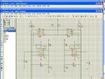
This is a circuit I want to do,I don't know how to i save a big photo with high resolution therefore i devide it to many parts:
these are the circuit i wanted to do:
converter_part1.JPGconverter_part2.JPGconverter_part3.JPG
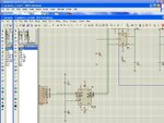
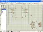
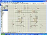
and this is a circuit that i used in my breadboard and used ONLY one comm port:
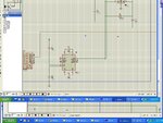
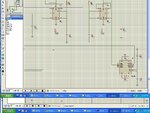
converter_part1_1.JPGconverter_part1_2.JPGconverter_part1_3.JPG
I have used a baterry to power for ICs.When i connected the GND of comm port to negative pole of battery it is not work but when GND is not connected I received what I send even when battery is not connected.I have checked V+, V- voltage and i received like this:
V+=5.6V and V-=6.2V.
TX =-2.1V and RX =0.8V when the GND pin of comm port is connected to the negative pole of battery
all measuring above when idle state.Would you help check it again?Thanks.
 

Attachments

  • converter_part1.JPG
    converter_part1.JPG
    181.3 KB · Views: 70

Would you let me know why this circuit not work!.In order to debug this circuit I have removed two 555 ICs and tied DE and RE of MAX 485 to VCC and GND respectly like this:**broken link removed**
and then I tied the GND of comm port to negatiive of 5V voltage suppply,when run the program that is post above, the result is like that:**broken link removed**
I measure the voltage of A,B outputs of RS485 and I received the result:
VA= 5.97V and VB= 5.8V.I checked all connnection but all are good.
But when the GND of comm port is not connected.I run program and the result like this:**broken link removed**
EVEN no matter the 5V voltage supply is connected or not.:???:
 

Attachments

  • circuit11.jpg
    circuit11.jpg
    109.3 KB · Views: 70
  • test1.jpg
    test1.jpg
    46.4 KB · Views: 62
  • run_result2.jpg
    run_result2.jpg
    106.2 KB · Views: 76
Last edited:

You are running a loop back circuit via level conversions. When the Ground is removed. It acts as a diode//R connection from end to end. The schematic looks ok to me... Your steady state voltages are wrong on the TX out and RX in.
Since the loop runs clockwise in the schematic.. Start verifying your known idle state voltages and follow each stage to get the expected output. WHen it looks wrong see if the chip is working as it should on each pin.
Thanks.I really appreciate, i am a very newbie in electronic and have many things to learn.Would you give me detail why when the Ground is removed. It acts as a diode//R connection from end to end, I try to understand but fail.I have simple the schematic to debug but i received the result is not expected.The circuit I have redraw is more simple but it AGAIN not work.Could You Take Some Of Your Precious Time And help me why this is happen in the schematic I have just post soon.I very confused about that.All things I had simulate in proteus and it is good but when wire in breadboard it not work and very complex to me.
 

Just verify transfer function ( input/output levels) of each stage starting from source TXD.
When it fails to make sense stop and examine all chip inputs. and check output load. Perhaps simple layout error or assy error or blown chip.
 
Just verify transfer function ( input/output levels) of each stage starting from source TXD.
When it fails to make sense stop and examine all chip inputs. and check output load. Perhaps simple layout error or assy error or blown chip.

Thanks.You are right, i have check max232 and it is not work.Now i have replace it but there is a problem that although I can send and receive data but it is not exactly there are many error in characters.I only transmit in very short distance.At first I have add termination resistor but It is don't effect.Do i really need termination resistor in a very short distance?
And could you show me why during i send data to comm port I used voltmeter to measure in TX but I have received between -6 to -8V .As far as i know the 232 standard have the voltage between-25V to 25V?
Now i have just add 120ohm between A and B lines and it work good but It good ONLY one direction.In the other direction I can received but it is wrong.I have check all.Both 2 circuit are same It make me confuse:???:
 
Last edited:

Tx = -7V is ok remember Rx threshold is ~1.2V but with hysteresis control, a bit more,. but +/-3V is even ok for short distance. More needed for longer cable.

YOu should not load with 120Ω. Make sure Tx pattern is OK, Levels, timing, polarity, pulse width, parity, data order LSB<>MSB, stop bits. etc.
 

Status
Not open for further replies.

Similar threads

Part and Inventory Search

Welcome to EDABoard.com

Sponsor

Back
Top