Continue to Site

Welcome to EDAboard.com

Welcome to our site! EDAboard.com is an international Electronics Discussion Forum focused on EDA software, circuits, schematics, books, theory, papers, asic, pld, 8051, DSP, Network, RF, Analog Design, PCB, Service Manuals... and a whole lot more! To participate you need to register. Registration is free. Click here to register now.

help with MQ137 NH3 sensor

Status
Not open for further replies.

meysaminter

Banned
Joined
Dec 19, 2009
Messages
59
Helped
0
Reputation
0
Reaction score
0
Trophy points
1,296
Activity points
0
Hi, there
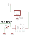
I am designing NH3 mesuing circuit . I want to use MQ137 sensor , but the aplication of sensor is unclear for me .the first problem is in calibration of sensor .first I must mesure the Rs of sensor in the air .is this resistor Ro ? if yes, why in the Diagram the Rs/Ro is obout 3 ? and then I must place the sensor in an area with the known Concentration and mesure the Rs . then how can I calculate the Concentration of gas in other situations? I know that the voltage across RL is misures by micocontroller . and Rs is calculated by the formula : Rs=((Vc/VRL)-1) × RL . after this stage I don't now what to do .
 

You will stand more chance of getting help if you provide some more information such as a link to the sensor data and your application circuit.

Keith
 

the sensor has 2 datasheets :
 

Attachments

  • MQ137.rar
    281.8 KB · Views: 200

Hello meysaminter,

If you want to use the sensor it to check the presence of NH3 in the air then use of a voltage comparator would have been the right choice.
But the word "measure" has changed everything. You need to use ADC with microcontroller.

Now listen:-

MQ-137 contains a variable resistor inside the sensor. The resistance across an A pin and a B pin varies depending on how much NH3 is in the air in the sensor. The more NH3, the lower the resistance.

The trick is, Instead of measuring the resistance directly, we measure the voltage level at the point between the sensor and a load resistor. The sensor and load resistor form a voltage divider, and the lower the sensor resistance, the higher the voltage reading will be. A microprocessor’s (like 16F876A) analog input pin is a good way to measure the voltage and gives us a reading between 0 and 1023. Higher values mean more NH3.

In the given circuit a 10K ohm load resistor is used in series with the sensor resistor.( Though the MQ-137 datasheet says to use a 200K ohm resistor. It’s on purpose.) Make sure you connect all the grounds together.

According to the datasheet the sensor has a 24-48 hour “break in” period. That is, the sensor needs to be turned on for 24-48 hours before the readings become stable.
 

Attachments

  • gasalyzerSchematic.png
    gasalyzerSchematic.png
    9.8 KB · Views: 199
Last edited:
It was some challenge to find out how to graphs are drawn,
i think i found the ideas and solutions behind this device...
I myself have never used these type of gas-sensors.

why in the Diagram the Rs/Ro is obout 3 ?
how can I calculate the Concentration of gas in other situations?
Rs=((Vc/VRL)-1) × RL . after this stage I don't now what to do .

Hope these help you out...............

Sensor graphs calibrated with 40ppm NH3
Gas_sensor_MQ137_NH3_pic_01.jpg

Sensor graphs calibrated with 50ppm Ethanol
Gas_sensor_MQ137_NH3_pic_02.jpg

Calculations
Gas_sensor_MQ137_NH3_pic_03.jpg

A simple entire circuit solution guide for gas leak alarm
Gas_sensor_MQ137_NH3_pic_04.jpg

KAK
 
kak111 and papunblg ,
thanks for your help . you are the best .;-)
 

It was some challenge to find out how to graphs are drawn,
i think i found the ideas and solutions behind this device...
I myself have never used these type of gas-sensors.


Hope these help you out...............

Sensor graphs calibrated with 40ppm NH3


Sensor graphs calibrated with 50ppm Ethanol


Calculations


A simple entire circuit solution guide for gas leak alarm


KAK


Hi kak

Thank you for your useful help .

A question :

How can i calculate Rscal ?
 

hello every one. Iam using this sensor for my project and as ive seen the graphs and the attached picture i have also the same question with the TS. Is the Rscal will be based on computation of i am going to assume the value of RScal in the range of 2k to 15K? please help us answer this question..

regards,
Mark
 

For finding RO (Sensor resistance in clean air):

we can measure output voltage of sensor in clean air and then calculate RS . According to datasheet in clean air (Rs/Ro)=3.3 . Ro=(Rs/3.3).
 

hi
Iam using this sensor for my project and as ive seen the graphs and the attached picture but i dont now why embeding the sensor in circuit in fact the driver circuit is my problem.please help me by sending a picture of circuit but not the cuircuit in datasheet.thanks
 

Status
Not open for further replies.

Part and Inventory Search

Welcome to EDABoard.com

Sponsor

Back
Top