Continue to Site

Welcome to EDAboard.com

Welcome to our site! EDAboard.com is an international Electronics Discussion Forum focused on EDA software, circuits, schematics, books, theory, papers, asic, pld, 8051, DSP, Network, RF, Analog Design, PCB, Service Manuals... and a whole lot more! To participate you need to register. Registration is free. Click here to register now.

[SOLVED] how to design a PIC board.

Status
Not open for further replies.

confusion

Junior Member level 3
Joined
Jan 6, 2012
Messages
25
Helped
0
Reputation
0
Reaction score
0
Trophy points
1,281
Activity points
1,516
hello!! i am designing a pic board for my project for the first time.!! and have no knowledge where and how to start. all i want to use is 8 leds. i read the datasheet of pic 16f877 and i will be using that. my question is
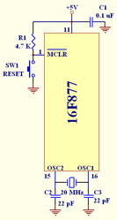
1)what besides crystal ckt.(2 capacitors and a crystal as specified in datasheet). and a reset circuit do i have to add in board.?
plz help!!
 
Last edited:

Almost done! Now read this: Interfacing LED To Microcontroller **broken link removed**

---------- Post added at 23:48 ---------- Previous post was at 23:47 ----------

also
https://www.bipom.com/applications/micro_interfacing.pdf

---------- Post added at 23:51 ---------- Previous post was at 23:48 ----------

PIC16F877_genused1.jpg


---------- Post added at 23:58 ---------- Previous post was at 23:51 ----------

See
**broken link removed**
for codes, circuit, picture, video
 
thanx papunblg!! from the links and circuit diagram . i understood the how to connect a crystal and reset circuit . but how do i program the board. i mean i need help with the bootloader thing. i saw some boards which uses isp cable for programming but how do i interface it with pic.
 

thanx again!! now i have an idea how to make a programmer board but now let me ask you a very dumb question but i dont really know this.. what should be done in order to enter the pic into programming mode. ??
 

pic-pg1-sch.gif


---------- Post added at 01:04 ---------- Previous post was at 00:50 ----------

Generally I use miKroC Pro to compile the program and make a .hex file.
Then use PicPGM program to transfer the .hex file to the PIC.

You place your pic micro on JDM board's IC base.-> Connect the board to your PCs com1 port. -> Run PICPGM -> The software will recognize your chip.--> select the .hex file to write-> select programme button to write the pic micro. Previous content will be erased and the new content will be written.

Remove the PIC micro and place it upon the IC socket of the programmer board. Now power the development/programmer board.

You can also program the micro chip without removing it from the develoment board. In the picture of the boards you will notice 6 pin connectors. From this connection points 6 wires will go to the 5 pins (and one ground) of the micro on the development board. It is called ISCP connection.

---------- Post added at 01:06 ---------- Previous post was at 01:04 ----------

now let me ask you a very dumb question but i dont really know this.. what should be done in order to enter the pic into programming mode. ??

No question is dumb.

---------- Post added at 01:18 ---------- Previous post was at 01:06 ----------

https://www.olimex.com/dev/pic-pg2.html
 
ok that is fine but my question is which pins of the pic16f877a should be connected to icsp while programming the pic chip??

---------- Post added at 01:43 ---------- Previous post was at 01:36 ----------

also if i choose to use a usb port instead of com port since many laptops do not have a serial port..then the whole design changes..u have design for that?
 

ok that is fine but my question is which pins of the pic16f877a should be connected to icsp while programming the pic chip??

There are several variations of the circuit to properly connect an ICSP Programmer/Debugger to the PIC. The following is very similar to the circuit I normally employ:

62_1330546904.jpg


Details of pic ICSP and how to use it for pic microcontrollers.

Microchip In-Circuit Serial Programming (ICSP) Guide

Only three lines are necessary, MCLR/VPP, PGC and PGD, for successful High Voltage Programming (HVP).

The PGM pin is only used for Low Voltage Programming (LVP), is not supported by the majority of PIC ICSP programmers/debuggers.


also if i choose to use a usb port instead of com port since many laptops do not have a serial port..then the whole design changes..u have design for that?

In reference to general serial communications or a USB based PIC ICSP programmer/debugger?

BigDog
 
confusion,
You are lucky enough to get an answer from Mr. Bigdoggure. And what a coincidence, I too, assembled my first pic programmer following a post of Mr. Bigdogguru!
 
thanx a lot Mr.bigdogguru !! now i totally understood the pin functions and connections of icsp cable with pic.
also a lot of thanx to papunblg

In reference to general serial communications or a USB based PIC ICSP programmer/debugger

yes it is for USB based PIC ICSP programmer/debugger. please tell me how to go about designing it.
 

You're requesting a PICkit clone. I personally do not have any experience with the PICkit or its clones, I use the Microchip ICD2, ICD3 and Real ICE.

However, there are numerous threads in the forum that discuss the construction of various PICkit clones which are USB based, a few of the available threads:

PicKit 2 FULL with TH components - Need help with layout

CB0703-PCB for "PICkit 2" DIY(Do It Yourself) fans

ICD2 compatible/clone for 18F4550

Project to replace CY7C64613 in the ICD2


The other option is to purchase either a genuine or clone PICkit:

**broken link removed**

**broken link removed**

There are also numerous clones available:

eBay Search - PICkit


If you are a novice with the PIC, you may want to consider purchasing either a genuine or clone PICkit rather than embarking on the journey of constructing of a unit.

BigDog
 
I'd recommend getting ICD2 compatible clone, very cheap and easily available... Mine happens to come from PIC16.com. JDM is great for programming, but to debug makes life much easier, and my MCD2 cost about the same as the parts would for a serial-port JDM

One thing I do now know... The PIC24 I'm "on now" can use 3 different sets of programming pins (CLK and DATA), PGC1 & 2 & 3 all work.. The config bits contain an entry that sets which set of pins the debugger is on but it can be programmed using any of the 3 sets (I have found)...

Most (Alll) PICs (I have) have a switch-on-delay config bit that can be enabled, so I'd (again, my experience only) just tie VPP (ICSP pin1 and most PIC's PIN 1, except 16f628/88 it's pin 5) to Vdd with a 1k restistor.. The startup delay cap isn't accounted for anymore...

If you get an MCD you'll never regret it (in my experience!)
Hi BD
NEAL

---------- Post added at 20:38 ---------- Previous post was at 20:31 ----------

Here's a "normal" one I use daily
**broken link removed**

The PIC seems pretty hardy, but get 2 just to test differences... I've managed to find (through my own faults probably) PICs with working no interal clocks, no working external clocks, dead pins, etc, so its always nice to have a reference one to compare...

I've only got 1 PIC24 at the moment and this is "her"
**broken link removed**

All for my fun, but take encouragement, a lot can be done!!
:-D All fun I hope, you can do anything "one step at a time", is the big lesson with PICs!! And they are pretty hard too..!
NEAL
 
I'd recommend getting ICD2 compatible clone, very cheap and easily available... Mine happens to come from PIC16.com. JDM is great for programming, but to debug makes life much easier, and my MCD2 cost about the same as the parts would for a serial-port JDM
L

Hi,

Have to ask where you can currently buy such a MCD2 at such a low price.


confusion
i saw some boards which uses isp cable for programming but how do i interface it with pic.

also if i choose to use a usb port instead of com port since many laptops do not have a serial port..then the whole design changes..u have design for that?

All the diy programmers need a pic chip to be programmed up in the first place.
As you say you are a beginner would strongly suggest you buy a ready made USB programmer such as the Pickit2, either Microchips own or a good clone line the Sure Electronics one.
They only cost as much as all the parts for a simple diy one, which can be problematic to build for some.

While that will allow you to program and debug the pic chips you may want the user program to communicate with the PC, in which case you can output Serial data from the Pic chip and run it through one of the many cheap Serial to USB converter dongles found on ebay.
Once you become more proficient you can get pic chips with usb comms onboard.
 
I don't like to use a name but mine came from sure-electronics... Ebay... Mine was about £13
NEAL

---------- Post added at 21:34 ---------- Previous post was at 21:23 ----------

[confused qwuote] They only cost as much as all the parts for a simple diy one [/confused qwuote]
I think i said that...

All the diy programmers need a pic chip to be programmed up in the first place
PICs can be *real* cheap ready programmed in bulk.... Look for BLOADER and there is bootloader stuff available for easy USB "firmware update" type setups (just like Arduino have, am I right?)
and
microchip'll let you send code to them (on a simple web page) for them to program on 1000's PICS and deliver them to your door, pure cheap. Only "scaling for the future", but good to remember... Bootloaders mean your users can update your stuff easily, you'll need them one day I would think... :)


Only the DIY programmers that give VPP a proper 12v (normally transisorised) will work with bare chips I know... My 1st emergency programmer was just 2x5v zeners, 2 resistors, a transistor and a 12v supply (as well as 5) and a DB9 (probably £25 in Maplins' with PSUs). There's an easy programmer, "PonyProg" (a windows/wine simple i2c device programmer). The MCD just brings the "proper" world to life, get one definately I can't recommend anything that is more fun... There's nothing worse than not knowing if your PICs dead or if one of your programming wires has un-soldered in a home made one, and it'll be useful for life more than likely!!!

Cool,
NEAL

---------- Post added at 21:47 ---------- Previous post was at 21:34 ----------

Sorry, I missed the crystal bit , dont let it worry you, they tend to work well...
If its got to be a 16f877......
The best things I find (size and placing without bending) are "crystal resonators" (Maplins').. 4Mhz - 20 Mhz, strap each side to 2 capacitors, from 10 to 30pf from ground (Pin 12) to each pin with the crystal acrross it (Pin 14 and 15), and it'll just tend to run, but dont touch it.. Break the copper track (if on stripboard!) so it's not finger-able..
I found it pain because there's no internal osc... The 16f887 has internal oscilator options, so saves you 2 pins anyway, worth a thought....
Cool,
NEAL
 
As I and my fellow colleagues have previously suggested, if you are a novice with with PIC family of MCUs, you may want to purchase a programmer/debugger from a reputable source. If you do decide on a clone, be aware that not all clones are created equal, many do not offer the full range of features found in the genuine Microchip programmer/debuggers.

Also, as wp100 and I have suggested, there are several advantages in purchasing a genuine PICkit or ICD from Microchip, one of the most important being support and customer service. From experience I can state without hesitation Microchips support and customer service is second to none. When the ICD3 was first release, I encountered issues with a unit I had just purchased due to a design flaw. Once Microchip had determine it was indeed a hardware issue with the ICD3, they immediately FedEx'd a new replacement unit with a return shipping label for the defective unit, now that is customer service.

I might also add the PICkit has several nice features which come in handy for the individual with limited resources, like a 3 channel logic analyzer and a UART tool, which many feature limited clones do not offer.

I you are currently in school, Microchip does offer a 25% discount for students as well.

If you have not already found the following online tutorials, you would most likely benefit greatly from studying them:

**broken link removed**

They are very professionally done, cover both the Baseline and Midrange PICs using both the MPASM Assembly and the Hi-Tech C Compiler.

The PIC16F877 you mentioned is a Midrange PIC, although the Baseline lessons cover material relevant to many of the PIC families.

Good Luck with your development board, if you have any additional issues feel free to post them in this thread.

BigDog
 
I "couldnt agree more" about buying from MicroChip direct you are right obviously. Normally, I'd happily give them my money, they are my favorite people on earth and I want them to make even better things and keep doing the stuff I love most, but for now that clone-one I've got has "survived", unscathed, and it must be the most active programmer on the planet for 9 months, plugged into "knock up" boards like that photo...

We are lucky to be in such an amazing world of silicon control, I want everyone to love PICs too, mega fun and keeping me learning and creating :)
We "overt the day of the singularity" by a few seconds everytime someone buys an MCD.. (humourous grin considering a discuassion with an
AI BigDog with XBoxKinnect and cannon could be part of "judgement day!) (nutty grin :)) )
https://singinst.org/?

Cool, :-D
NEAL
 
This is as simple as it gets for an 877A, a crystal, a reset, and 5 pins for ICSP... I've stuck a chip-socket next to some ports to give me scanning LED Matrix for fun
**broken link removed**

So, I hope this'll encourage your "experience" by showing that "any fool with half a brain (or 80% for me right now I've been made right-temporal-lobeless but no longer epileptic :)" can do *real good, useful things with PICs*, switches, lights etc, and one day those "little sparks" may be the basis for a "proper" project or make a "tool" you need to knock up one day. Never use a 555 again.! The way I've learned the is to look around the practical side of things, at least to the point ... The idea behind this "board layout" (Veroboard artistry normally means placing chips and links "on the fly", I'm a very in-the-mind circuit builder for some reason) I believe is to test clocked-serial and PMP type inter-chip joinery, funny enough suggested (on EDA) by the BD a time ago when I was 1st playing with LEDs...

Once you've got the 877 mastered, you'll see it is *so* useful you should just keep a few knocking around... The only shame is the need for an external crystal, there are others 88x line PICs with internal clocks that at least give you an MCU in 3 pins, 0, +, and the reset pin... Don't ever let the programmer set the chip to internal oscilator, (the MCD2 won't let you do it but the JDM programmer does!) and at the same time "ignore the MCLR/reset pin" (both in the "Config Register") on, on older chips especially, it "Locks them in time" as if one-time-programmable Some you can return with a "Vpp before Vdd" option on the standard MCDs, but I still have 3 or 4 16f628A's I try in vain to revive, that are just stuck playing the same routine forever now... Because the PORTB value is being altered by the running code, the programmer can't "get in" to talk to the chip and will never change, an annoyance but not the end of the world....
**broken link removed**
Buy a few PICs rather than, sometimes they do blow, but I've got the same PIC24 in this board "3.5" and the 1st PIC24 , my "Board3",

This is a cracking picture, it's my WIFI (PIC24) board and the PIC24 and the 877, it'll be cool when it's switched on and coded but looks nice!
**broken link removed**


A bit of a gallery here, all fun encouragement!!
**broken link removed**
regards
Neal
 

Once you've got the 877 mastered, you'll see it is *so* useful you should just keep a few knocking around... The only shame is the need for an external crystal, there are others 88x line PICs with internal clocks that at least give you an MCU in 3 pins, 0, +, and the reset pin... Don't ever let the programmer set the chip to internal oscilator, (the MCD2 won't let you do it but the JDM programmer does!) and at the same time "ignore the MCLR/reset pin" (both in the "Config Register") on, on older chips especially, it "Locks them in time" as if one-time-programmable Some you can return with a "Vpp before Vdd" option on the standard MCDs, but I still have 3 or 4 16f628A's I try in vain to revive, that are just stuck playing the same routine forever now... Because the PORTB value is being altered by the running code, the programmer can't "get in" to talk to the chip and will never change, an annoyance but not the end of the world....

I have never encounter this issue with any PIC when using the ICD2, ICD3 or Real ICE.

Are the configuration settings made in code or the MPLAB IDE?

Can you post the specific code and configuration settings that causes the issue?

Has this only happened with the PIC16F628A or have you encounter a similar situation with other PICs? If so, what were the other model numbers?

BigDog
 

My latest MCD does "warn" not to set IntOsc and VPP-Tied-to-VDD....
My "Maplins'" programmer doesn't warn, so once a chip is programmed to run "Just with 5v, (o external VPP tie-resistor) and the IntOsc set, 628's especially are know to "Lock"... I've lots!!
https://www.electro-tech-online.com/microcontrollers/39202-16f628a-cant-enter-programming-mode.html

Basically the processor is too busy to respond... WIth the VPP-Tied-uip reproramming works if I unplug the crystal for a second...
Later chips (16f88) respond to VPP-Before-VDD normally, but I've tried *a lot* of times and the 628a's are just locked in time playing the "atique clock" movement game forever...

Neal
 

One thing I've just found, the DSPIC30F3014 fits in "almost the same" layout board too, more fun for other times!!!,

My 1st DSPIC30F3014 has just turned up in the post (I seem to be working through 80's 90's and now 000's technologies again), and it fits in the 877a hole almost perfectly, with only a bit of a change around... It takes 5v so seems a "bit of a step-backwards?" from the PIC24, but the FFT access has to make it worth the "jolly"....

Just with a move of the 2 programming pins and adding VSS&VSS in 2 extra places, the programmer connected and made it blink in no time. The Oscilator is on the same 2 pins, and the 8MHZ I used on the 877a works in 16x mode fine, but admitedly just the same as using the internal built-in-oscilator.. I'm sure I will test to see the top speed as printers get scrapped and crystal emerge from their innards... A 20Mhz clock ran at 16x would sound nice, but I only learn by experience and little point really, but I'll know when I've done it....

Could be a busy weekend.. :)
**broken link removed**
NEAL
 

Status
Not open for further replies.

Part and Inventory Search

Welcome to EDABoard.com

Sponsor

Back
Top