Continue to Site

Welcome to EDAboard.com

Welcome to our site! EDAboard.com is an international Electronics Discussion Forum focused on EDA software, circuits, schematics, books, theory, papers, asic, pld, 8051, DSP, Network, RF, Analog Design, PCB, Service Manuals... and a whole lot more! To participate you need to register. Registration is free. Click here to register now.

what does 'step' mean in this passage..to increase?'

Status
Not open for further replies.

the_falcon

Member level 4
Joined
May 28, 2010
Messages
72
Helped
0
Reputation
0
Reaction score
0
Trophy points
1,286
Location
Toronto
Activity points
1,811
hi all,
can you guys make me understand this passage.

Selectivity is the degree of distinction made by the receiver between the desired signal and unwantedsignals. You will find the better the ability of the receiver to reject unwanted signals, the better itsselectivity. The degree of selection is determined by the sharpness of resonance to which the frequency-determining circuits have been engineered and tuned. You usually measure selectivity by taking a seriesof sensitivity readings. As you take the readings, you step the input signal along a band of frequenciesabove and below the circuit resonance of the receiver; for example, 100 kilohertz below to 100 kilohertz above the tuned frequency. As you approach the tuned frequency, the input level required to maintain agiven output level will fall. As you pass the tuned frequency, the required input level will rise. Inputvoltage levels are then compared with frequency. They can be plotted on paper or you might view themon an oscilloscope. They would appear in the form of a response curve. The steepness of the responsecurve at the tuned frequency indicates the selectivity of the receiver.

falcon
 

"Step the input signal" would be better replaced with "step the input signal frequency". So, you make measurements at frequencies either side of the receiver frequency that you a "tuned" to.

Keith
 
Stepping the frequency means to change it a bit at a time. In the example given (plus and minus 100kHz around the frequency of interest) changes of perhaps 5 or 10kHzat a time might be chosen, and measurements made at each of them.
 
Thank you very much for trying to helping me. If I try to replace with input signal with input signal frequency then the later part of the passage is confusing to me as they mention that the input level fall for the tuned frequency and goes higher for the frquencies offset from the tuned frequency.


Falcon
 

It is only the "step the input signal" part that you highlighted in bold that should be changed to "step the input signal frequency", not everywhere the term "input signal" is used.

Keith.
 
Ok..Thanks for the speedy response. I have a small confusion on the passge. If the input signal level falls for the tuned frequency, then does it mean that the circuit works just fine with the lowest signal level for the correctly tuned frequency and it would also try to work for the frequencies little offset from the tuned frequency, provided the signal level is quite high..? Sorry if its so trivial but I am getting confused with this thing. Hows the input information signal(modulating signal) level's strength(votlage level in precise) that comes along with a carrier wave(modulated signal) with certain amplitude determines the working of the ciruit tuned at some other frequencies than the correct tuned frequency.

thanks again


falcon
 

It does depend on the nature of the "signal" e.g. the type of modulation but yes, you can receive (and demodulate) signals which are off frequency depending on how strong they are. If you consider a conventional AM radio (say on medium wave) then even if you are slightly off frequency you can still hear the station. If the station is very strong then you can be quite a long way off tune an still hear it. That causes problems if you live near a powerful transmitter - you cannot receive weak stations near the strong station's frequency.

Keith.
 
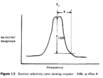
I see. Thanks for the information. Then in this logic, if I try to plot the selectivity for say an AM receiver, then I will probably get a U shaped curve of signal magnitude levels plotted against the frequency in the X axis..? So a response curve usually means a U shaped curve ? Because this is what they mentioned in the passage which I posted in the beginning.

For example, in this figure the selectivity graph is totally in the opposite way. Could u tell me as whats happening here?
graph.png


One more small doubt:

Usually selectivity is expressed in dBc? or in dB? Sometimes its just expressed in dB too.Selectivity basically mentions the difference in the signal strength needed to hear the station inspite of being off tuned from the right frequency?

A Selectivity of 70 dB is better than the one having say around 35 dB or is it the opposite way around.?

thanks

falcon
 
Last edited:

Status
Not open for further replies.

Similar threads

Part and Inventory Search

Welcome to EDABoard.com

Sponsor

Back
Top