Continue to Site

Welcome to EDAboard.com

Welcome to our site! EDAboard.com is an international Electronics Discussion Forum focused on EDA software, circuits, schematics, books, theory, papers, asic, pld, 8051, DSP, Network, RF, Analog Design, PCB, Service Manuals... and a whole lot more! To participate you need to register. Registration is free. Click here to register now.

Question about charging concept of different battries.

Status
Not open for further replies.

Qaisar Azeemi

Full Member level 5
Joined
Feb 11, 2011
Messages
315
Helped
16
Reputation
32
Reaction score
15
Trophy points
1,298
Location
Peshawar, Pakistan, Pakistan
Activity points
3,829
Hi friends!

Whenever we want to charge a battery..... all we have to do is to in-feed it a specific amount of current. This charging current starts a Reverse reaction in the chemicals of the battery and the number of electrons changed in both plates and thus the battery gets charged.....

Now my Question is that why we use different chargers for different types of batteries? that is according to my knowledge the charger of a 6v lead acid battery can not charge the battries of other chemistries (Li-ion, NiMH etc)
what is the reason behind this? why the charger of one battery type do not charge the the other battery type of same rating?

thank you
 

Hi Qaisar!

Yes, annoying isn't it? And although you are right in that the recharging principle is fundamentally the same (i.e. electrons poked back in permit the "recharging" chemistry to occur) there are two main reasons why we can't:

a. Some chemistries are particular about the maximum instantaneous charge currents. NiCd for example, can tolerate extremely high charging currents - 10C+ for example, whereas lead acid batteries require a much lower rate. Excessive charging current may damage a battery thermally or via gas production rates in excess of what can be recombined internally or vented safely.

b. The end-of-charge point (and its detection) differs between chemistries. If this point is missed, then overcharging may (will) occur. Overcharging is tolerated to different extents by each of the chemistries - Pb-acid is quite forgiving, for example (it will just sit and quietly bubble it's electrolyte away) whereas Li-ion will burst into flames! Some chemistries use the terminal voltage to indicate being fully charged (and thus the end-of-charge is defined as a specific [often temperature compensated] voltage), others use cell temperature, others use the time derivatives of these (dV/dt, dT/dt), others use the instantanous charging current etc etc...

Cheers :)
 
Thank you very much Thylacine. your post is really helpful to me. so what about Pb-Acid battries? can i charge them up to a maximum of 30% of their ampere hour rating. can it be brust on overcharging? do you have any useful links/tutorial links about battries charging theory and their chargers?
 

You have partially answered yourself. Just because of their chemistry and material use to build. I will give a layman example. Consider lead Acid battery as concrete water tank and lithium ion battery as water balloon. Both will except flow of water but when they are full, concrete water tank will accept no more water and excess water will be overflown. but when the balloon will be filled it will just explode.

Same case in the batteries. A lead acid acid will form gases by overcharging and release them through vents(this shorten the battery life). but they can accept constant current charges up to a point.
This is not the case with lithium-ion. You need to apply pressure( as in water ) i.e. voltage(as in battery) to its safe elasticity(as in balloon) limit i.e. its nominal voltage(as in battery).
 
Nice example and nice explaination Sajjad :) thank you. so it means i can charge my flooded lead acid batteries 24v(2 12v in series) 200AH by appling 27v on its terminals and a current of a minimum of 10% of its AH rating (i.e; 20A ) to 30% of its AH rating i.e; 60A.

OR

for a 6v 4.5ah sla battery the charging current must not be more than (4.5*30)/100 = 1.35A ....

and minimum current must not be less than 10% of its AH rating 0.45A for above example.

am i right in my concept????
 

Qaisar Azeemi said:
so it means i can charge my flooded lead acid batteries 24v(2 12v in series) 200AH by appling 27v on its terminals and a current of a minimum of 10% of its AH rating (i.e; 20A ) to 30% of its AH rating i.e; 60A.
All you want to know about batteries could be found in battery university. Please read the following article, I think it will be helpful and will answer to your questions.


Alexandros
 

Nice example and nice explaination Sajjad :) thank you. so it means i can charge my flooded lead acid batteries 24v(2 12v in series) 200AH by appling 27v on its terminals and a current of a minimum of 10% of its AH rating (i.e; 20A ) to 30% of its AH rating i.e; 60A.

OR

for a 6v 4.5ah sla battery the charging current must not be more than (4.5*30)/100 = 1.35A ....

and minimum current must not be less than 10% of its AH rating 0.45A for above example.

am i right in my concept????

Well i have been experimenting on batteries for more than 15 months now. i wont suggest you charge batteries in series with 27V or with a constant voltage source.

Reason:

If i say that my single 12V battery is charged when my battery voltage reaches 13.5V same as the power supply, i.e. 27V for two batteries in series. Then following issues can occur.
if both batteries are at different charging levels due to different brand or different battery health or your carelessness then suppose the battery B1 has 12V on it and battery B2 has 12.5V on it. when you start charging them then both battery voltages will increase gradually and simultaneously. When SUM of voltages on both batteries will reach at 27V then it dosent mean that both the batteries are charged. the 12.5V battery is now on 14V and is being overcharged and 12V battery is on 13V and its not being charged.

For charging batteries in series consider 3 state charger
and for single battery consider 2 stage charger or single stage charger.
 

Can you give me any link for a 3 state charger. its schemetic and tutorial???

---------- Post added at 11:11 ---------- Previous post was at 10:56 ----------

secondly i am charging my battries using LM317 regulator and this circuit is also limiting the current i.e; it reduces the current gradually to the battries and the voltages on the terminals of the batteries increases gradually. i charged SLA battries till now but when i tested the flooded LA batteries connected in series to the UPSes to provide them 24v at their input i note that some of the flooded battries reached up to 14.5V that is quite higher than the normal full charge voltage of 13.5v for lead acid batteries... are they overcharged?? however you better know in our country the power failure problem is frequent. such frequent power failure problem dont let the battries to charge fully but i was astonished when i noted their voltages.. some was on round about 12.3V and some was on 14.5v approx: (There are 6 5kva UPSes in our office with 2 flooded lead acid battries each). i am confused in all this.

for my experiment on SLA battries (two 12v in series) both have a voltage difference of hardly 0.1V; so they didn't show such problem yet and i am successfully and normally using them.

---------- Post added at 11:48 ---------- Previous post was at 11:11 ----------

oh yes you was right. i just check it again. most of the series connected battries to the UPSes one battery is overcharged and the other is less charged. in one set one battry have 12.3V while the other have approximately 15V.... but i am astonished the overcharged one was not heated up.. it was quite cool..... :-/
 

Such a powerful system needs huge battery banks and you are charging them with Lm317! are you nuts? This will take your whole life to charge those batteries.
I wont recommend flooded batteries as i have experienced, a little heat in the batteries makes the water evaporate, plus these batteries charging is usually detected by their gravity gauge.
I would recommend you to use Sealed lead acid batteries. Charging flooded type or sealed lead acid batteries with voltage 13.4-13.8V is fine and don't do harm to it but its a slow charging, you cant even use a 2 stage charger on sealed lead acid batteries as i will describe.

First you need to know what a 3 stage charger is.

1st. stage is constant current mode. in this stage fixed current is injected into batteries till the batteries voltage reaches 13.8V, if both batteries are not at the same voltage level this stage assures that they do. after that 2nd stage. in 2nd stage constant voltage is applied (14.4-15V) till when very little current is left going in the batteries. for healthy batteries if current is less than 100mA and for partially healthy batteries its less than 400mA. At this stage the batteries are charged. then at stage 3 the voltage is further reduced to 13.4.-13.8V,this is standby float charging.

You need a big power supply regulated by lm317 or lm338. Since you need high current to charge batteries fast so you need a powerful external pass power transistor. and you may go up to 30 Amps of charging current.

For your batteries to live longer, dont discharge them below 70% of their current capacity.

I will try to make a simple schematic for your understanding if i get time and try to post it.

---------- Post added at 12:02 ---------- Previous post was at 11:56 ----------

oh yes you was right. i just check it again. most of the series connected battries to the UPSes one battery is overcharged and the other is less charged. in one set one battry have 12.3V while the other have approximately 15V.... but i am astonished the overcharged one was not heated up.. it was quite cool..... :-/

Notice when you use the ups then one battery will be discharged and loosing its health while the other battery will no be discharged fully. Then at sometime you will replace that dead battery with a new one. Then the new one will not be fully discharged and the old one will lose its health eventually. This process will be on going and you will keep paying for it.
 
This is the basic circuit. Its not perfect but i hope when you get hold of it then you will be able to make it perfect.

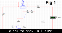
FIG1:
Notice that J1 switch (which can be replaced by a Relay) is on the left side and Q1 is not connected to any thing. in fact Q1 will be connected to your controller or voltage comparator which will be either high or low. You can see the voltage is 14.4V.

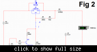
FIG2:
When 5V is connected to the transistor Q1 then you can see that voltage is further dropped to 13.5V.

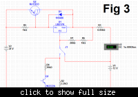
FIG3:
Now switch is on the left right side and the resistor R2 and R4 are effectively disconnected. The only effective resistor left in this loop is 0.056 ohms. so 1.25/0.056 is almost 22 Amps. you can set any Amps depending on the value of R3.

Few things are missing in this circuit as due to lack of time and i hope you will figure it out of yourself.
1. to shift from stage 2 to stage 1 you need to monitor current. There are many current sense circuit on the net.I prefer it on the high side.
2. There is no check on Q2. even in stage 2 if batteries are too big they would suckkk such a huge amount of current that Q2 will go pufffff. so you need to limit the current also. there are many current limiting current on the net too.

Just be careful about power dissipation and heat issues while designing your circuit.


Such a powerful system needs huge battery banks and you are charging them with Lm317! are you nuts? This will take your whole life to charge those batteries.
I wont recommend flooded batteries as i have experienced, a little heat in the batteries makes the water evaporate, plus these batteries charging is usually detected by their gravity gauge.
I would recommend you to use Sealed lead acid batteries. Charging flooded type or sealed lead acid batteries with voltage 13.4-13.8V is fine and don't do harm to it but its a slow charging, you cant even use a 2 stage charger on sealed lead acid batteries as i will describe.

First you need to know what a 3 stage charger is.

1st. stage is constant current mode. in this stage fixed current is injected into batteries till the batteries voltage reaches 13.8V, if both batteries are not at the same voltage level this stage assures that they do. after that 2nd stage. in 2nd stage constant voltage is applied (14.4-15V) till when very little current is left going in the batteries. for healthy batteries if current is less than 100mA and for partially healthy batteries its less than 400mA. At this stage the batteries are charged. then at stage 3 the voltage is further reduced to 13.4.-13.8V,this is standby float charging.

You need a big power supply regulated by lm317 or lm338. Since you need high current to charge batteries fast so you need a powerful external pass power transistor. and you may go up to 30 Amps of charging current.

For your batteries to live longer, dont discharge them below 70% of their current capacity.

I will try to make a simple schematic for your understanding if i get time and try to post it.

---------- Post added at 12:02 ---------- Previous post was at 11:56 ----------


Notice when you use the ups then one battery will be discharged and loosing its health while the other battery will no be discharged fully. Then at sometime you will replace that dead battery with a new one. Then the new one will not be fully discharged and the old one will lose its health eventually. This process will be on going and you will keep paying for it.


thank you very much for such a nice explanation sajjad bhai. Actually i will use 3 LM338s as given in its data sheet to get a maximum of 15 ampere current to charge 150AH to 200AH flooded lead acid battries and to SLA as well. and i also want to develop/design switch mode power supply based charger to reduce the amount of heat generated but first i will try to make LDO type using LM338s.


secondly your given pictures in your second post is the basic concept for a 3 stage charger??? if yes the according to my experiments to charge a 12v SLA battery when i set 14v at the output of my charger circuit that i make it by using LM317 to charge a small 7ah 12v SLA battery ; its output is reduced to 11.5v and then it is gradually increased to 13.5v while the current is reduced from high to an appropriate low level....

so from your circuit i come to an understanding that i have to design a circuit that charge the battery with its(Charger's) out put of 14.4v and when the out put of the battery(7ah, 12v SLA in my case) reaches up to 13.5v then i should reduce the output voltage of my charger to 13.5V using my microcontroller....... am i right????

secondly i can't understand the purpose of Q2 (PNP Darlington pair) here??? is it easily available in the market.

Best regards and salam

M Qaisar Azeemi
 

Q2 is easily available in the market.
When Charging batteries with specific voltage and you see a voltage reduced when connected to batteries have mainly 1 good reason:
Your battery is connected in the opposite polarity of the charger. obviously if you measure the voltage at your batteries terminal then it will show the battery voltage not the charger voltage. Its just like charging capacitor.Consider a big capacitor in an RC circuit when you charge it then it invites a huge amount of current which is limited by the resistor, since the current is huge then max voltage is dropped across the resistor. When charges starts to add up in capacitor the current starts to reduce and voltage across the resistor starts to drop and increase across capacitor.
Same case it the batteries. The resistor in this case is normally (transformer winding resistance + Wire resistances + Regulator impedance) If these resistances are low then the rise in voltage will be much quicker.
LM338 only gives 5 Amps and only when its input-output difference is less than 10V.

Follow up my circuit and use a basic book of electric circuits by flyod. In the chapter of regulators you will find the protection circuit also.
 

Status
Not open for further replies.

Part and Inventory Search

Welcome to EDABoard.com

Sponsor

Back
Top