Continue to Site

Welcome to EDAboard.com

Welcome to our site! EDAboard.com is an international Electronics Discussion Forum focused on EDA software, circuits, schematics, books, theory, papers, asic, pld, 8051, DSP, Network, RF, Analog Design, PCB, Service Manuals... and a whole lot more! To participate you need to register. Registration is free. Click here to register now.

Transformers and Opto couplers --- isolators

Status
Not open for further replies.

iVenky

Advanced Member level 2
Joined
Jul 11, 2011
Messages
584
Helped
37
Reputation
76
Reaction score
35
Trophy points
1,318
Location
College Station, Texas
Activity points
6,124
How do you say that transformers and opto couplers act as isolators and prevent any shock from the other circuit?

Thanks in advance.
 

How do you say that transformers and opto couplers act as isolators and prevent any shock from the other circuit?

Thanks in advance.

Can you explain that little more? Or give some sugested schematic what zou have in mind.

Optocouplers used a lots for isolation purposes, signal leveling,....

Transformators of course galvanic isolation, .....

Galvanic isolation in power equipment refers to the fact that the output power circuit is electrically and physically isolated from the input power circuit. Electrical isolation is accomplished using an isolation transformer. Physical isolation means that the output power wiring does not touch or connect to the input wiring.

All personal computers already have galvanic isolation between the input power and the computer logic built in. This is a requirement of international safety agencies in order to prevent shock hazard. Therefore, the addition of another transformer is redundant.

Many people mistakenly believe that galvanic isolation corrects noise on ground (earth) wiring. This is not correct. In fact, all galvanic isolation transformers only isolate the power wires, but pass the ground wire straight through.

**broken link removed**
 
Last edited:

(..) and prevent any shock from the other circuit?
Read: with very low conductivity (=many Ohms) and very low capacitive coupling between parts that carry high voltage, and parts that you might touch.

In practice, optocouplers and transformers (=magnetic fields) are some of the few ways you can do this, while still passing energy and/or data across that boundary. Transformers mostly for energy transfer, optocouplers mostly for data transfer, on/off switch signals and the like.
 
  • Like
Reactions: iVenky

    iVenky

    Points: 2
    Helpful Answer Positive Rating
Read: with very low conductivity (=many Ohms) and very low capacitive coupling between parts that carry high voltage, and parts that you might touch.

I can understand how it is possible with transformer(increases the input impedence) but how do you do this using opto coupler? I mean how do you say that optocoupler increases the input impedence?

Thanks in advance.
 

I mean how do you say that optocoupler increases the input impedence?

How do you mean that ? Optocoupler separate circuits opticaly!!!

Impact on primary circuit which need to be isolated is only in usage of resistor to limit current for LED in optocoupler.

http://www.datasheetcatalog.org/datasheets/228/466209_DS.pdf

**broken link removed**


Perhaps you can find something from this :
**broken link removed**


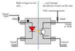
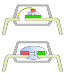
Example of optocoupler :
bb.jpg 220px-Optoisolator_topologies_both.svg.png
 
Last edited:

Hello my friend
At transformers , we have 2 independent winding ( at least) on a core , thus the circuit between them , just is with magnetic circuit ( not electrical) .
And about opto couplers , consider , that you want give a command signal to the gate of triac , that works with 500 volts . if you want give this command with a simple micro controller , your micro controller , can receive , the noises , from power line , or if your triac be don't intact , it is possible , that your control system be don't intact , but we can optimize , it with using an opto coupler , such as MOC3021 ( for triac s and SCR s ). thus , if your triac become destroyed , your control system can not , destroy , just a cheap MOC , can destroy.
Best Wishes
Goldsmith

I think I am quite getting your point. So if we assume that the triac gets destroyed due to some very huge current then this current can't flow through the microcontroller simply because there's no reverse transmission in an optocoupler. But in a transformer we do have reverse transmission right? I mean if the current increases in the secondary due to some reason then it should increase in the primary too right?

Thanks in advance.
 

Again Hi
No , at transformers , we have not problem too , but opto couplers , are better , for lower currents . and my mean is that suppose , that the Gate of triac is short circuit to MT1 And MT2 ( destroyed triac ) . thus that high voltage can destroy your micro controller . thus , for safety , we can use opto couplers or transformers.
Respectfully
Goldsmith
 

Status
Not open for further replies.

Part and Inventory Search

Welcome to EDABoard.com

Sponsor

Back
Top