Continue to Site

Welcome to EDAboard.com

Welcome to our site! EDAboard.com is an international Electronics Discussion Forum focused on EDA software, circuits, schematics, books, theory, papers, asic, pld, 8051, DSP, Network, RF, Analog Design, PCB, Service Manuals... and a whole lot more! To participate you need to register. Registration is free. Click here to register now.

potentiometer and set resistance

Status
Not open for further replies.

curtcon

Newbie level 3
Joined
Jan 1, 2012
Messages
4
Helped
0
Reputation
0
Reaction score
0
Trophy points
1,281
Activity points
1,321
I have a potentiometer set in place and working, I would like to have a switch that allows the potentiometer to work as normal when off and to have a 1k ohm resistance when switched on. I would like to stay with a single rocker switch if possible. Can a 5 pin relay be used for what i am trying to make or will resistance to work thru a relay? is there something that will work as a relay that is made just for 2 different resistance settings that would work better?

I can just use a 2 position switch if need be but would like to keep it uniform to the switches I have now.

Thank you for any advice
 

Happy new Year!

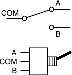
If you use a throw switch with one input and two outputs, like this image
58_1325455125.gif
 

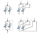
Here is few switched pot.meters....
PotMeter_Switch.jpg
 

Happy new yours to you as well

Well the style I have doesn't offer it in a throw switch. Is there a way to run the 2 different resistances thru a relay of some sort?

---------- Post added at 23:20 ---------- Previous post was at 23:12 ----------

Here is few switched pot.meters....
View attachment 66604

Sorry i am just learning this so the image doesn't help me.

Basically the switch would be to add a resistance of 1k ohm on top of the potentiometers already 0.45 ohm min resistance.

---------- Post added at 23:33 ---------- Previous post was at 23:20 ----------

Like a remote control car with a pre set cruise control rocker switch. Or would a throw switch be the best way of achieving this?
 

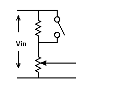
Is this what you are thinking of?

potplusfixed.gif


With the switch, which can be any type, is closed, you have only the potentiometer in circuit. With the switch open you have the additional resistor in series with it.
 

@curtcon: There's one detail that still needs clarification from you. You speak of a potentiometer but your descriptions can also be taken to mean that it's being used as a variable resistor. The difference between the two is that a variable (adjustable) resistor (also called a rheostat) is just that: a resistor whose resistance can be adjusted while a potentiometer (pot) is like a pair of resistors whose relative values can be adjusted. A pot can be used as a variable resistor, but then technically it's no longer being used as a potentiometer.

Some of the suggestions already given to you assume that the pot is being used as a potentiometer. It will help give you a more concrete solution if you could find a way to clarify the point.

Another thing is that you said
Basically the switch would be to add a resistance of 1k ohm on top of the potentiometers already 0.45 ohm min resistance.
When the 1k resistor is switched into effect, do you want the pot adjustment to still affect the overall resistance or do you want the 1k to act alone?
 

Is this what you are thinking of?

potplusfixed.gif


With the switch, which can be any type, is closed, you have only the potentiometer in circuit. With the switch open you have the additional resistor in series with it.

I am going for the added 1k resistor when the switch is on but could work this way as well. So the pot meter is the lower one with the arrow pointed to it and the top one is the 1k resistor? So basically the signal would go thru the path of least resistance (switch) when the switch is turned on? would this work correctly with out any irregularities in resistance?

---------- Post added at 04:46 ---------- Previous post was at 04:26 ----------

@curtcon: There's one detail that still needs clarification from you. You speak of a potentiometer but your descriptions can also be taken to mean that it's being used as a variable resistor. The difference between the two is that a variable (adjustable) resistor (also called a rheostat) is just that: a resistor whose resistance can be adjusted while a potentiometer (pot) is like a pair of resistors whose relative values can be adjusted. A pot can be used as a variable resistor, but then technically it's no longer being used as a potentiometer.

Some of the suggestions already given to you assume that the pot is being used as a potentiometer. It will help give you a more concrete solution if you could find a way to clarify the point.

Another thing is that you said

When the 1k resistor is switched into effect, do you want the pot adjustment to still affect the overall resistance or do you want the 1k to act alone?


Sorry I am not so good with correct terminology of electrical components. I am working with a pot meter in my truck that is attached to my gas pedal (sensor for throttle), the pot meter at idle is 0.45 resistance, I am trying to make a switch to give me a high idle for a few reasons. When the 1k resistor is added it will give me the idle speed I am looking for (in park only). I am still looking for the pot meter to function the same as it did but just with the added 1k resistor. I know I can wire it thru a throw switch as posted before and also by a double switch like I was planning. I have a set of automotive rocker switches installed for other things. I am hoping to keep the same type of rocker switch (single throw on/off). I am thinking of instead doing it the way Syncopator posted provided it will not have any spikes or irregularities.

I guess I should have named the post pot meter with added 1k resistor.
 

I am going for the added 1k resistor when the switch is on .....

To do that you would need a double throw switch, i.e. a switch with three connections.

So the pot meter is the lower one with the arrow pointed to it .....

Yes, that's the symbol for a normal potentiometer. A preset potentiometer would have a flat end to the line instead of a point.

So basically the signal would go thru the path of least resistance (switch) when the switch is turned on?

Yes.

... would this work correctly with out any irregularities in resistance?

I see no reason why any irregularities should be introduced, certainly not to the resistance value.
With an instantaneous demand for more power, the engine of a much older auto might cough a bit, but a modern engine management system, as yours obviously is, will take are of this.
 
Thank you all for the help.
 

Status
Not open for further replies.

Part and Inventory Search

Welcome to EDABoard.com

Sponsor

Back
Top