We all know what a motor is and what it does. The simplest way to run a motor is to just connect it to a power source. For a DC motor, that would mean, just connecting the motor to the DC voltage that the motor was rated for (or less). But, can you control the speed?
Yes. The simplest method is to control the speed of the motor by controlling the voltage the motor runs off. Imagine we have a 12V motor. If you run it off 12V, you get maximum speed (you can get more at higher voltage, but let's not go over rated specifications!). So, simple logic dictates that as we decrease the voltage to the motor, the speed must decrease. You can use a simple LM317 regulator to adjust the voltage to the motor and thus the speed.
But, this method of speed control has one huge disadvantage - inefficiency when using a linear regulator (and you may find the motor not running at all at lower voltages). Let's talk about the inefficiency. If we use a linear regulator to give 6V output from 12V input, where does the other 6V go? Well, that is dissipated as heat and this is the inefficiency I'm talking about. Let's say that the motor will draw 1A at 6V. So, your power supply output rated at 12V is regulated to 6V (at 1A current). And 6V is dropped and dissipated as heat. So, useful power = 6W. Wasted power = 6W. And you have an efficiency of only 50%. See?
The other method is PWM and this is far more efficient. Instead of converting the remaining power to heat, it "chops" the signal (that has a constant frequency) and lets the remaining to go through.
The fraction of the period for which the signal is on is known as the duty cycle. The average DC value of the signal can be varied by varying the duty cycle. The duty cycle can be anywhere between 0 (signal is always off) to 1 (signal is constantly on). If the signal has +12 V while it is on and 0 V during off condition, then by changing the duty cycle of the signal, any voltage between 0-12 V can be simulated.
With a duty cycle of 0, you get 0 output. With a duty cycle of 25% (0.25), you get 25% power. With duty cycle of 60% (0.6), you get 60% power. With duty cycle of 100% (1), you get full power. So, this provides an efficient way of controlling the power to a load. So, if power to a motor is controlled like this, the motor's speed can be controlled.
So, to control the speed of the DC motor, I have used PWM. The PIC16F877A has a CCP module, that allows us to use PWM at a hardware level.
Timer 2 is used as the time base. PR2 sets the PWM frequency according to the formula:
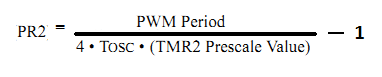
The ratio of CCPR1L to (PR2 + 1) sets the duty cycle. If PR2 = 249, CCPR1L = 125 gives 50% duty cycle. If PR2 = 249, CCPR1L = 180 gives 72% duty cycle. And so on.
CCP1CON is the CCP control register (image taken from PIC16F877A datasheet):
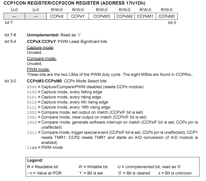
As you can see from the register details above, to set CCP1 to PWM mode, bits 3 and 2 of CCP1CON must be set to 1. The values of bits 1 and 0 do not matter. In my code, I have set CCP1CON = 12, but you can use one of
CCP1CON = 12
CCP1CON = 13
CCP1CON = 14
CCP1CON = 15
Any one of the above four values of CCP1CON will set CCP1 for PWM mode.
In the code, I did not use the mikroC libraries for PWM since I wanted to demonstrate the use of the registers associated with PWM.
Here is the code:
I've added comments to the code to make it as self-explanatory as I could.
There's one trick I used here and I will clarify that here.
I have used a 16MHz oscillator. With PR2=249, frequency is 16kHz.
CCPR1L must lie between 0 and (PR2 + 1), so in this case, between 0 and 250.
The ADC result can vary between 0 and 1023, 1023 corresponding to maximum speed. So, I've used divide by 4 to scale down the ADC result to between 0 and 255. However, a value of 255 can not be assigned to CCPR1L as it is beyond the maximum allowable value. So, I've set an upper bound of 240, above which the motor will run at maximum speed. I've also set a lower bound below which, PWM is stopped and motor is stopped.
Here's the circuit (you can see the generated PWM signal in the oscilloscope):
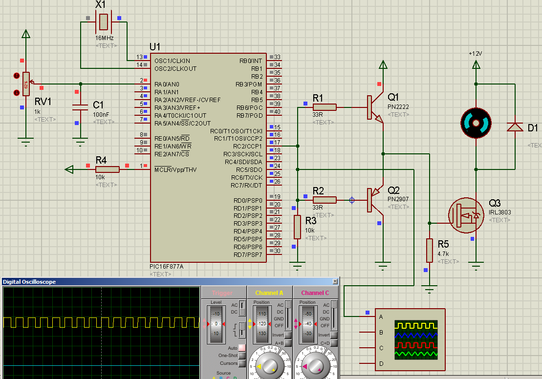
Q1 and Q2 form a totem-pole driver to drive the logic-level MOSFET IRL3803. A power MOSFET can not be fully turned on at a voltage of 5V, and requires voltages above 8V to be fully on. But a logic-level MOSFET can be fully turned on at 5V. To avoid drive complexity, I've used a logic level MOSFET. D1 is the freewheel diode.
Reference documents:
PIC16F877A datasheet: ww1.microchip.com/downloads/en/devicedoc/39582b.pdf
IRL3803 datasheet: fenykapu.free-energy.hu/pajert59/irl3803.pdf
Yes. The simplest method is to control the speed of the motor by controlling the voltage the motor runs off. Imagine we have a 12V motor. If you run it off 12V, you get maximum speed (you can get more at higher voltage, but let's not go over rated specifications!). So, simple logic dictates that as we decrease the voltage to the motor, the speed must decrease. You can use a simple LM317 regulator to adjust the voltage to the motor and thus the speed.
But, this method of speed control has one huge disadvantage - inefficiency when using a linear regulator (and you may find the motor not running at all at lower voltages). Let's talk about the inefficiency. If we use a linear regulator to give 6V output from 12V input, where does the other 6V go? Well, that is dissipated as heat and this is the inefficiency I'm talking about. Let's say that the motor will draw 1A at 6V. So, your power supply output rated at 12V is regulated to 6V (at 1A current). And 6V is dropped and dissipated as heat. So, useful power = 6W. Wasted power = 6W. And you have an efficiency of only 50%. See?
The other method is PWM and this is far more efficient. Instead of converting the remaining power to heat, it "chops" the signal (that has a constant frequency) and lets the remaining to go through.
The fraction of the period for which the signal is on is known as the duty cycle. The average DC value of the signal can be varied by varying the duty cycle. The duty cycle can be anywhere between 0 (signal is always off) to 1 (signal is constantly on). If the signal has +12 V while it is on and 0 V during off condition, then by changing the duty cycle of the signal, any voltage between 0-12 V can be simulated.
With a duty cycle of 0, you get 0 output. With a duty cycle of 25% (0.25), you get 25% power. With duty cycle of 60% (0.6), you get 60% power. With duty cycle of 100% (1), you get full power. So, this provides an efficient way of controlling the power to a load. So, if power to a motor is controlled like this, the motor's speed can be controlled.
So, to control the speed of the DC motor, I have used PWM. The PIC16F877A has a CCP module, that allows us to use PWM at a hardware level.
Timer 2 is used as the time base. PR2 sets the PWM frequency according to the formula:
The ratio of CCPR1L to (PR2 + 1) sets the duty cycle. If PR2 = 249, CCPR1L = 125 gives 50% duty cycle. If PR2 = 249, CCPR1L = 180 gives 72% duty cycle. And so on.
CCP1CON is the CCP control register (image taken from PIC16F877A datasheet):
As you can see from the register details above, to set CCP1 to PWM mode, bits 3 and 2 of CCP1CON must be set to 1. The values of bits 1 and 0 do not matter. In my code, I have set CCP1CON = 12, but you can use one of
CCP1CON = 12
CCP1CON = 13
CCP1CON = 14
CCP1CON = 15
Any one of the above four values of CCP1CON will set CCP1 for PWM mode.
In the code, I did not use the mikroC libraries for PWM since I wanted to demonstrate the use of the registers associated with PWM.
Here is the code:
Code:
//-------------------------------------------------------------------------------------------------------

//Programmer: Syed Tahmid Mahbub
//Compiler: mikroC PRO for PIC v4.60

unsigned int ADR;

void main() {
     PORTC = 0;
     TRISC = 0; //all PORTC pins output
     PORTA = 0;
     TRISA = 0x01; //RA0 input for pot
     CMCON = 7; //Disable analog comparators
     T2CON = 0; //Prescaler 1:1, TMR2 off
     ADCON1 = 14; //AN0 only analog
     ADC_Init(); //mikroC initializes ADC
     CCP1CON = 12; //PWM mode
     PR2 = 249; //16kHz PWM frequency
     while (1){
           ADR = ADC_Get_Sample(0) >> 2; //Get ADC reading for channel 0
           //and divide reading by 4
           if (ADR < 10){ //Setting lower bound
              TMR2ON_bit = 0; //Stop Timer and so stop PWM
              TMR2 = 0; //Clear Timer
              RC2_bit = 0; //Clear PWM output
           }
           else{
                if (ADR > 240){ //Setting upper bound
                   TMR2ON_bit = 0; //Stop Timer and so stop PWM
                   TMR2 = 0; //Clear Timer
                   RC2_bit = 1; //Keep PWM output high
                }
                else{ //Within upper and lower bounds
                      CCPR1L = ADR; //Set PWM duty cycle
                      TMR2ON_bit = 1; //If not on, turn on TMR2. If on, keep on
                }
           }
     }
}

//-------------------------------------------------------------------------------------------------------
I've added comments to the code to make it as self-explanatory as I could.
There's one trick I used here and I will clarify that here.
I have used a 16MHz oscillator. With PR2=249, frequency is 16kHz.
CCPR1L must lie between 0 and (PR2 + 1), so in this case, between 0 and 250.
The ADC result can vary between 0 and 1023, 1023 corresponding to maximum speed. So, I've used divide by 4 to scale down the ADC result to between 0 and 255. However, a value of 255 can not be assigned to CCPR1L as it is beyond the maximum allowable value. So, I've set an upper bound of 240, above which the motor will run at maximum speed. I've also set a lower bound below which, PWM is stopped and motor is stopped.
Here's the circuit (you can see the generated PWM signal in the oscilloscope):
Q1 and Q2 form a totem-pole driver to drive the logic-level MOSFET IRL3803. A power MOSFET can not be fully turned on at a voltage of 5V, and requires voltages above 8V to be fully on. But a logic-level MOSFET can be fully turned on at 5V. To avoid drive complexity, I've used a logic level MOSFET. D1 is the freewheel diode.
Reference documents:
PIC16F877A datasheet: ww1.microchip.com/downloads/en/devicedoc/39582b.pdf
IRL3803 datasheet: fenykapu.free-energy.hu/pajert59/irl3803.pdf