In most cases where you want to control an AC load, a triac or SCRs will be used. However, it is not easy to drive a triac or SCR. The drive requirement for the triac or SCR makes it sometimes difficult to control it as we want. One thing is that we can not turn the triac or SCR on or off as we desire, because once we turn it on, it latches and stays on until the next zero crossing or until current stops flowing through it. Also, driving a triac with reference to MT1 (or A1) is not as straightforward as we would want.
However, a MOSFET can be controlled as we want. Set the gate high (with a sufficient voltage) and current can flow from drain to source. Set the gate low and current can no longer flow. Convenient!
However, a MOSFET can only be used to control DC loads since it is a unidirectional switch - current flow can be controlled when it is flowing from drain to source, but can not be controlled from source to drain. So, certainly it can not be used to control AC loads. Right?
Well, directly, it can not be used to control AC loads the same way you'd control DC loads. But, with some clever circuitry, it can be used to control AC loads. And here's how:
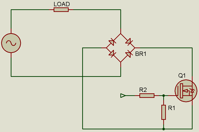
Perhaps you don't see how it works now. But consider the two diagrams below, which show the flow of current during the two AC half cycles. I'm sure you'll get it better then.
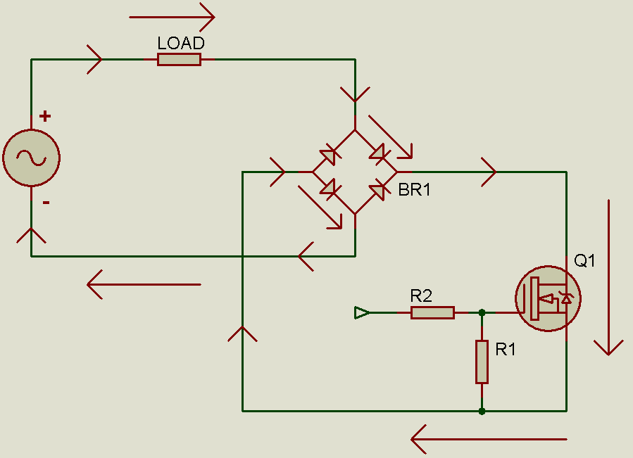
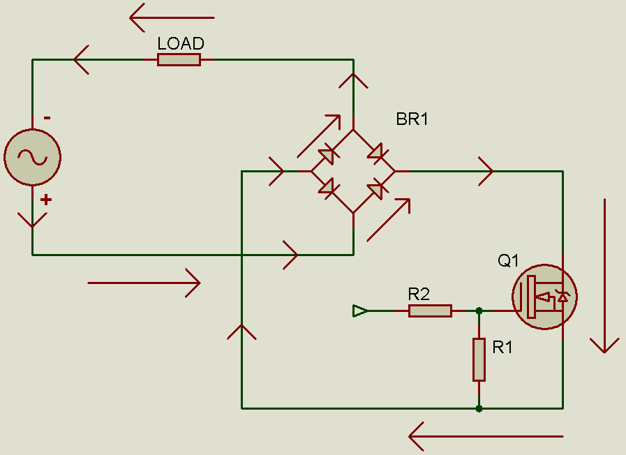
As you can see, due to the bridge rectifier, the MOSFET always "sees" a DC voltage as the drain is always positive with respect to the source. Thus, with this combination of the bridge rectifier and MOSFET, by controlling a DC switch - the MOSFET, you can control the AC load.
The MOSFET must be turned on fully by driving it high by at least 8V above source level - 8V with respect to source.
So, you can turn the MOSFET on and off at any time and accordingly turn the load on and off as required. This makes driving the AC load so easy!
However, a MOSFET can be controlled as we want. Set the gate high (with a sufficient voltage) and current can flow from drain to source. Set the gate low and current can no longer flow. Convenient!
However, a MOSFET can only be used to control DC loads since it is a unidirectional switch - current flow can be controlled when it is flowing from drain to source, but can not be controlled from source to drain. So, certainly it can not be used to control AC loads. Right?
Well, directly, it can not be used to control AC loads the same way you'd control DC loads. But, with some clever circuitry, it can be used to control AC loads. And here's how:
Perhaps you don't see how it works now. But consider the two diagrams below, which show the flow of current during the two AC half cycles. I'm sure you'll get it better then.
As you can see, due to the bridge rectifier, the MOSFET always "sees" a DC voltage as the drain is always positive with respect to the source. Thus, with this combination of the bridge rectifier and MOSFET, by controlling a DC switch - the MOSFET, you can control the AC load.
The MOSFET must be turned on fully by driving it high by at least 8V above source level - 8V with respect to source.
So, you can turn the MOSFET on and off at any time and accordingly turn the load on and off as required. This makes driving the AC load so easy!