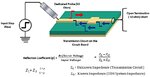
Time Domain Reflectometry is the analysis of conductor lines (interconnects)by sending a pulsed signal into the conductor and then examining the reflection of that pulse. A TDR transmits a short rise time pulse along the conductor. If the conductor is of a uniform impedance and is properly terminated, the entire transmitted pulse will be absorbed in the far-end termination and no signal will be reflected toward the TDR. Any impedance discontinuities will cause some of the incident signal to be sent back towards the source. By examining the polarity, amplitude, frequencies and other electrical signatures of all reflections; tampering or interconnect discontinuity may be precisely located
Time Domain Reflectometry is the analysis of conductor lines (interconnects) by sending a pulsed signal into the conductor and then examining the reflection of that pulse. A TDR transmits a short rise time pulse along the conductor. If the conductor is of a uniform impedance and is properly terminated, the entire transmitted pulse will be absorbed in the far-end termination and no signal will be reflected toward the TDR. Any impedance discontinuities will cause some of the incident signal to be sent back towards the source.
By examining the polarity, amplitude, frequencies and other electrical signatures of all reflections; tampering or interconnect discontinuity may be precisely located.
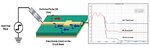
TDR: Working Principle
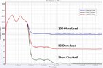
With TDR, step pulse voltage is input into the transmission circuit and the voltage reflected in the transmission circuit is measured over time. The characteristic impedance of the circuit board is then calculated from the voltage drop in the reflected voltage.
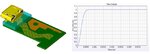
TDR Simulation Result of Transmission Line in Smart phone from USB to Chip
TDR Pulse (step waveform) is very important. Rise Time value specifies the rise time of incident TDR pulse. The resolution of a TDR measurement system is directly related to the rise/fall time of the incident pulse. Rise time is specified with either a 10%-90% or a 20%-80% definition.
For example, consider a 20* timestep rise time for a 10%-90% definition, there will be 20 time steps between the time where the waveform has a value of 0.1 to the time it reaches a value of 0.9.
Initial glitch on TDR response Since the instantaneous TDR response is directly calculated from V/I, it reveals the initial glitch on TDR response. It is due to the zero current flowing through at the time = 0