The basic of comparator:
Comparator is one of the mode of Op-Amp circuit. It is pretty simple in configuration like this image below: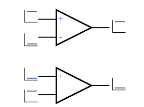
The output of the comparator is high if the non-inverting input voltage is higher than the inverting input pin. And the output is low if the non-inverting pin is lower than in voltage reading than the inverting pin. Here, we can take one pin as a reference and the other pin as an input pin. This is a totally simple operation. But there are some problems using in this condition while you are controlling something like a switch or relay or a load. Because, if the input voltage is almost the same as the reference voltage, the output will fluctuate. Check this image carefully.

The output is fluctuating for a very short time. This will definitely kill the relays if this is not conditioned. You may think about adding capacitor filters but that will not improve it. To solve this problem, we need to use the comparator circuit as a Schmitt-Trigger circuit or a comparator with hysteresis.
Here, a resistor R2 is used as a feedback resistor. This feedback resistor works as our hysteresis control resistor. Think in a simple way, whenever the input Vin is lower than the reference voltage, the output will be high. Then the feedback resistor will carry a minor current to the reference pin which increases the pin voltage a little. That makes the reference voltage a little higher than the present Vin voltage. So to turn the output off, the Vin pin has to be a little extra higher than the previous reference voltage. But once it is higher than the present reference voltage, the output will be low. Again the feedback resistor will draw some current from the reference pin which will actually reduce the actual reference voltage by a little. Now what? the Vin pin needs to be lower than this voltage (actual reference voltage + voltage droop due to the feedback resistor). This way the hysteresis works.
This hysteresis helps to control the output from fluctuating at the same input voltage range. That protects relays from chattering ensuring longer life.
If you want to know the calculations you can read this article here.
Now, we can apply the comparator circuit in out project.
Circuit diagram:

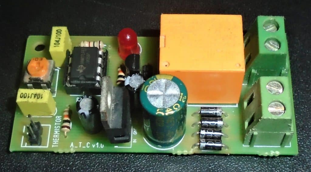
Here, a common Op-Amp LM358 is used where the R6 is our feedback resistor. Tuning the potentiometer RV1, we can set our temperature range. Then sensor RT1 is a 10KOhms NTC type temperature sensor. When the temperature is higher than the setpoint, the relay will be turned on and the heater is off. The same circuit can be used for cooling purposes too connecting a cooler in the other terminal of the relay.
PCB:
Read the full article.