Hi Dear All
Thank you for reading my blogs .
As i promised , i came back with more discussions about class D amplifiers and SMPS ( Switch mode power supply) systems :
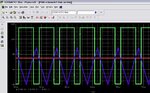
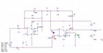
below you can see 2 picture , one of them a circuit to make PWM ( not SPWM ) and the other the waveforms .


As you can see , i compared the triangle wave with a constant DC voltage . thus it given an square wave without identical on and off time ( the duty cycle changed ).
Thus , with changing the DC voltage we will be able to control the D.C ( Duty Cycle ) at our desired range .
Some notes about it's spectrum :
It will has two main section :
1st: high frequency component
2nd: constant value .
And as we know , the avg value of this function , will given by :1/T integral ( from zero up to ton ) Vmax dt .
Thus after taking an integral from PWM , ( or as a matter of fact low pass filtering ) we won't have high frequency components , and we will have a DC voltage that given by :
Vmax.D.C
Ok I'll come back
Best Wishes for all of you .
Goldsmith
Thank you for reading my blogs .
As i promised , i came back with more discussions about class D amplifiers and SMPS ( Switch mode power supply) systems :
below you can see 2 picture , one of them a circuit to make PWM ( not SPWM ) and the other the waveforms .
As you can see , i compared the triangle wave with a constant DC voltage . thus it given an square wave without identical on and off time ( the duty cycle changed ).
Thus , with changing the DC voltage we will be able to control the D.C ( Duty Cycle ) at our desired range .
Some notes about it's spectrum :
It will has two main section :
1st: high frequency component
2nd: constant value .
And as we know , the avg value of this function , will given by :1/T integral ( from zero up to ton ) Vmax dt .
Thus after taking an integral from PWM , ( or as a matter of fact low pass filtering ) we won't have high frequency components , and we will have a DC voltage that given by :
Vmax.D.C
Ok I'll come back
Best Wishes for all of you .
Goldsmith
 I want to share you some simple...