What exactly is impulse response?
Mathematically speaking an impulse response is the response of a system to an input which is a dirac function (i.e. infinty at t=0 and zero everywhere else). But physically speaking what does this exactly mean? Impulse response of a system is very important factor because it tells you how long the system takes for it to become steady (i.e. to enter into the steady state) after an application of a sudden disturbance (a shock for example). This plays a major role in the control engineering. We would be enjoying our lives if everything goes smooth but if something bad happens suddenly then it would take a lot of time to recover from that. It depends on the person. If the person is really stubborn then he would recover fast and continue his life. But if the person is very weak in mind then he would not recover at all. The worst case is that he might lose his mind completely and become unstable (As Joker used to say -"All you need is one bad day to lose your mind"). So our mind is also a system. It is necessary that we need to build a strong system considering the sudden disturbances that might occur in the future.
Let's come back to Electronics. Consider that you have given a constant input say 5V to system and you are measuring the output. Suddenly what you are doing is that you are reducing the input to 0V. The system won't go to steady state immediately. It would take some time for it reach the steady state. (Note that reducing 5V to 0V is not an impulse mathematically but it is also a sudden disturbance and impulse response is a general term used to characterize the system). The time depends on the system. Let us consider three important systems and I will stop with that-
1) RC low pass filter:-
The Response of an RC low pass filter can be found in many ways. All that you need to do is to solve the governing differential equations and apply the initial conditions. The derivation is there in "Circuit Analysis" by Hayt and refer that book. The general solution which everybody should know is
v(t)= A e-t/RC.
In order to find the impulse response of a RC lpf it would be better if you could use Laplace transform (provided there is no initial energy across any element (cap or inductor). You can try the derivation yourself. If it contains any initial energy say 5V across Cap initially then you have to consider that as 5V supply in parallel with the Capacitor and then apply Laplace transform.
After solving using Laplace transform and its inverse we get
v(t) = (1/RC) e-t/RC
(Here I have basically assumed that there is no voltage across capacitor initially). We all know that voltage across the cap can't change instantaneously. But this is true for all input except for a dirac function or its derivative. Hence the voltage across the cap raises instantaneously from 0V to 1/RC and then it decays slowly.

Similarly you can do the same for a RL lpf.
2) RC high pass filter:
The impulse response of a RC high pass filter can be found using Laplace transform and we get
v(t) = delta(t) - 1/RC e-t/RC
So initially the output is infinite and then it reduces to 0 from the negative side. This is easy to understand because the capacitor voltage is charged in the direction as shown in the figure with a voltage 1/RC and hence the voltage across the resistor is the negative of it. (the direction of i(t) is also shown)

As you can there is no problem of long transition time in the above systems. These are first order systems and don't pose that much trouble. But here comes the second order system that can cause a long transition time if not designed perfectly - RLC.
Consider an RLC system either parallel or in series. I basically assume that there is no initial energy across any element.
Then depending on the value of 'alpha' and 'wo' the system might be over damped, critically damped and under damped. (The general solutions are given in Hayt).
After solving the differential equations it can be shown that
alpha = 1/ 2RC for parallel RLC and alpha= R/2L for series RLC.
wo = 1/ sqrt(LC)
If alpha> wo we get over damped, if alpha =wo we get critically damped and if alpha < wo. This can proved mathematically (Refer Hayt).
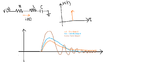
Here's the image.

( It's easy to see that at the time just before applying the disturbance the current as well the voltage is zero hence it is also 0 at the time just after applying the input disturbance because the current can't change instantaneously for an inductor and as well as the voltage across the cap can't change instantaneously)
The output waveform can be anything basically. (both voltage and current have a similar waveform except for the constant term. If you know the one you can find the other using basic expressions for capacitors ,inductors and Resistors).
RLC is an example for a band pass filter.
The above equations are worth memorizing because you will encounter this throughout your course.
But note that we can have band pass filter using other combinations also. In such cases there is no other go you have to find out the transfer function using Laplace transform and then find out its inverse to find out the impulse response.
That's all. Hope this helps.
Refer Hayt for if you wish to understand how we got those equations. The reason why I wrote this in my blog is because I thought that these equations are very important and it would be better if you could remember these equations.
Mathematically speaking an impulse response is the response of a system to an input which is a dirac function (i.e. infinty at t=0 and zero everywhere else). But physically speaking what does this exactly mean? Impulse response of a system is very important factor because it tells you how long the system takes for it to become steady (i.e. to enter into the steady state) after an application of a sudden disturbance (a shock for example). This plays a major role in the control engineering. We would be enjoying our lives if everything goes smooth but if something bad happens suddenly then it would take a lot of time to recover from that. It depends on the person. If the person is really stubborn then he would recover fast and continue his life. But if the person is very weak in mind then he would not recover at all. The worst case is that he might lose his mind completely and become unstable (As Joker used to say -"All you need is one bad day to lose your mind"). So our mind is also a system. It is necessary that we need to build a strong system considering the sudden disturbances that might occur in the future.
Let's come back to Electronics. Consider that you have given a constant input say 5V to system and you are measuring the output. Suddenly what you are doing is that you are reducing the input to 0V. The system won't go to steady state immediately. It would take some time for it reach the steady state. (Note that reducing 5V to 0V is not an impulse mathematically but it is also a sudden disturbance and impulse response is a general term used to characterize the system). The time depends on the system. Let us consider three important systems and I will stop with that-
1) RC low pass filter:-
The Response of an RC low pass filter can be found in many ways. All that you need to do is to solve the governing differential equations and apply the initial conditions. The derivation is there in "Circuit Analysis" by Hayt and refer that book. The general solution which everybody should know is
v(t)= A e-t/RC.
In order to find the impulse response of a RC lpf it would be better if you could use Laplace transform (provided there is no initial energy across any element (cap or inductor). You can try the derivation yourself. If it contains any initial energy say 5V across Cap initially then you have to consider that as 5V supply in parallel with the Capacitor and then apply Laplace transform.
After solving using Laplace transform and its inverse we get
v(t) = (1/RC) e-t/RC
(Here I have basically assumed that there is no voltage across capacitor initially). We all know that voltage across the cap can't change instantaneously. But this is true for all input except for a dirac function or its derivative. Hence the voltage across the cap raises instantaneously from 0V to 1/RC and then it decays slowly.
Similarly you can do the same for a RL lpf.
2) RC high pass filter:
The impulse response of a RC high pass filter can be found using Laplace transform and we get
v(t) = delta(t) - 1/RC e-t/RC
So initially the output is infinite and then it reduces to 0 from the negative side. This is easy to understand because the capacitor voltage is charged in the direction as shown in the figure with a voltage 1/RC and hence the voltage across the resistor is the negative of it. (the direction of i(t) is also shown)
As you can there is no problem of long transition time in the above systems. These are first order systems and don't pose that much trouble. But here comes the second order system that can cause a long transition time if not designed perfectly - RLC.
Consider an RLC system either parallel or in series. I basically assume that there is no initial energy across any element.
Then depending on the value of 'alpha' and 'wo' the system might be over damped, critically damped and under damped. (The general solutions are given in Hayt).
After solving the differential equations it can be shown that
alpha = 1/ 2RC for parallel RLC and alpha= R/2L for series RLC.
wo = 1/ sqrt(LC)
If alpha> wo we get over damped, if alpha =wo we get critically damped and if alpha < wo. This can proved mathematically (Refer Hayt).
Here's the image.
( It's easy to see that at the time just before applying the disturbance the current as well the voltage is zero hence it is also 0 at the time just after applying the input disturbance because the current can't change instantaneously for an inductor and as well as the voltage across the cap can't change instantaneously)
The output waveform can be anything basically. (both voltage and current have a similar waveform except for the constant term. If you know the one you can find the other using basic expressions for capacitors ,inductors and Resistors).
RLC is an example for a band pass filter.
The above equations are worth memorizing because you will encounter this throughout your course.
But note that we can have band pass filter using other combinations also. In such cases there is no other go you have to find out the transfer function using Laplace transform and then find out its inverse to find out the impulse response.
That's all. Hope this helps.
Refer Hayt for if you wish to understand how we got those equations. The reason why I wrote this in my blog is because I thought that these equations are very important and it would be better if you could remember these equations.