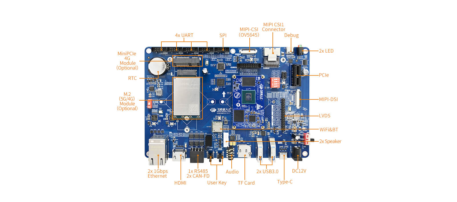
The Forlinx OKMX8MP-C development board is equipped with two native CAN buses. However, in certain product development scenarios, there is a need for additional CAN buses. This article will introduce a method for SPI to CAN conversion, providing engineers with a reference.
• The model of the SPI to CAN chip is MCP2518. This chip is capable of converting to CAN-FD. If only CAN functionality is required, you can refer to this method for porting MCP2515 or other chips;
• The driver for the MCP2518 chip in this porting process is sourced from the i.MX8MQ's firmware code. The MCP2518 chip is already ported by default in the processor.
Add:
vi OK8MQ-linux-kernel/drivers/net/can/rx-offload.c
Add:
Add:
vi OK8MP-linux-kernel/drivers/net/can/spi/Kconfig
Add:
Get: CONFIG_CAN_MCP251X=y
Change to: # CONFIG_CAN_MCP251X is not set
Add: CONFIG_CAN_MCP25XXFD=y
Add:
vi OK8MP-linux-kernel/arch/arm64/boot/dts/freescale/OK8MP-C.dts
Add:
From:
Change to:
After completing the above modifications, you can compile and burn the OKMX8MP-C development board with the newly generated image.
Connect the MCP2518 chip to the SPI2 interface, start the OKMX8MP-C development board, and then use the ifconfig -a command to view it, and you can see that there is one more CAN node.
Originally published at www.forlinx.net.
Description
• The FETMX8MP-C SoM has two native SPI buses. Currently, the pins of SPI1 are being used for LED and UART3 functions, while SPI2 is configured as a normal SPI2 interface. Taking SPI2 to CAN conversion as an example, the process involves porting the SPI to CAN chip;• The model of the SPI to CAN chip is MCP2518. This chip is capable of converting to CAN-FD. If only CAN functionality is required, you can refer to this method for porting MCP2515 or other chips;
• The driver for the MCP2518 chip in this porting process is sourced from the i.MX8MQ's firmware code. The MCP2518 chip is already ported by default in the processor.
1. Porting the MCP2518 chip driver
Create a folder named "mcp25xxfd" under the path "OK8MP-linux-kernel/drivers/net/can/spi/". Place the relevant files (including .c files, .h files, Makefile, Kconfig, etc.) in this folder.2. Complete the definition of can _ rx _ offload _ add _ manual function.
vi OK8MQ-linux-kernel/include/linux/can/rx-offload.hAdd:
vi OK8MQ-linux-kernel/drivers/net/can/rx-offload.c
Add:
EXPORT_SYMBOL_GPL(can_rx_offload_add_manual);
3. Modify Makefile and Kconfig under the previous directory SPI/
vi OK8MP-linux-kernel/drivers/net/can/spi/MakefileAdd:
vi OK8MP-linux-kernel/drivers/net/can/spi/Kconfig
Add:
4. Modify the driver configuration file and compile the MCP2518 into the kernel
vi OK8MP-linux-kernel/arch/arm64/configs/OK8MP-C_defconfigGet: CONFIG_CAN_MCP251X=y
Change to: # CONFIG_CAN_MCP251X is not set
Add: CONFIG_CAN_MCP25XXFD=y
5. Configure the clock in the device tree
vi OK8MP-linux-kernel/arch/arm64/boot/dts/freescale/OK8MP-C.dtsAdd:
6. Find a pin to use as the interrupt pin of the chip
GPIOUNK1IO21 is used as an interrupt pin here.vi OK8MP-linux-kernel/arch/arm64/boot/dts/freescale/OK8MP-C.dts
Add:
7. Modify in the ecspi2 node of the device tree
vi OK8MP-linux-kernel/arch/arm64/boot/dts/freescale/OK8MP-C.dtsFrom:
Change to:
After completing the above modifications, you can compile and burn the OKMX8MP-C development board with the newly generated image.
Connect the MCP2518 chip to the SPI2 interface, start the OKMX8MP-C development board, and then use the ifconfig -a command to view it, and you can see that there is one more CAN node.
Originally published at www.forlinx.net.