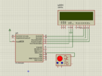
This is the mikcroC code for counting the external pulses frequency Using CCP1 module,
It will show values from 4Hz to 2Khz properly
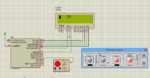
proteus diagrams herer


and also project files (MikroC+proteus ) View attachment 100035
Code:
/* Compiler: MikroC pro
    Author   : Ltsharma
    PIC16F628A - 4Mhz */

sbit LCD_RS at RA4_bit;
sbit LCD_EN at RB0_bit;
sbit LCD_D4 at RA0_bit;
sbit LCD_D5 at RA1_bit;
sbit LCD_D6 at RA2_bit;
sbit LCD_D7 at RA3_bit;

sbit LCD_RS_Direction at TRISA4_bit;
sbit LCD_EN_Direction at TRISB0_bit;
sbit LCD_D4_Direction at TRISA0_bit;
sbit LCD_D5_Direction at TRISA1_bit;
sbit LCD_D6_Direction at TRISA2_bit;
sbit LCD_D7_Direction at TRISA3_bit;
// End LCD module connections
long countrev;
char capture = 0;
unsigned int rpm_timer;
long rpm1;
char RPM[10];


void interrupt()
{
        bit pulse_state ;

        if(PIR1.TMR1IF)
        {
                countrev = 0;
                PIR1.TMR1IF=0;
        }

        if(PIR1.CCP1IF)
        {
                PIR1.CCP1IF = 0;
                switch(pulse_state)
                {
                        case 0:                       //if 1st folling edge reset tmet1 to 0
                        TMR1L = 0;
                        TMR1H = 0;
                        pulse_state = 1;
                        break;

                        case 1:                                  //if 2nd falling edge calculate time
                        rpm_timer = TMR1L;                                 // Get the first 8-bit TIMER1 Counter
                        rpm_timer = rpm_timer+(TMR1H << 8);    // Get the last 8-bit TIMER1 Counter
                        countrev = (int)(60000/rpm_timer);
                        pulse_state = 0;
                          break;

                }


        }

}


void main() {
    TRISB=0X08;                                       // Pin B3 set as CCP1 Input
   cmcon=0X07;
   CCP1CON = 0b0100;                             // Capture every falling edge
  T1CON = 0x31;                                 // Timer1 (Prescale = 8)
  PIE1.TMR1IE = 1;                              // Enable Timer1 overflow Interrupt
  PIR1.TMR1IF = 0;                              // TMR1 overflow cleared
  PIE1.CCP1IE = 1;                              // enable interrupt capture
  PIR1.CCP1IF = 0;                              //clear CCP flag
  INTCON.PEIE = 1;                              // Enables all low-priority peripheral interrupts
  INTCON.GIE = 1;                               // global interrupts

  Lcd_init();

  lcd_cmd(_lcd_clear);

  while(1){
  rpm1 = countrev;

  longtostr(rpm1,RPM);           // Convert to long int to string

  LCD_out(1,1,RPM);
        rpm1 = 0;


 }
 }
It will show values from 4Hz to 2Khz properly
proteus diagrams herer
and also project files (MikroC+proteus ) View attachment 100035