Continue to Site

Welcome to EDAboard.com

Welcome to our site! EDAboard.com is an international Electronics Discussion Forum focused on EDA software, circuits, schematics, books, theory, papers, asic, pld, 8051, DSP, Network, RF, Analog Design, PCB, Service Manuals... and a whole lot more! To participate you need to register. Registration is free. Click here to register now.

ZN414 (equivalents and derivates diagrams)

Status
Not open for further replies.

andreidaniel

Member level 2
Joined
Sep 18, 2010
Messages
42
Helped
1
Reputation
5
Reaction score
2
Trophy points
1,288
Location
Romania, Iasi City
Activity points
1,818
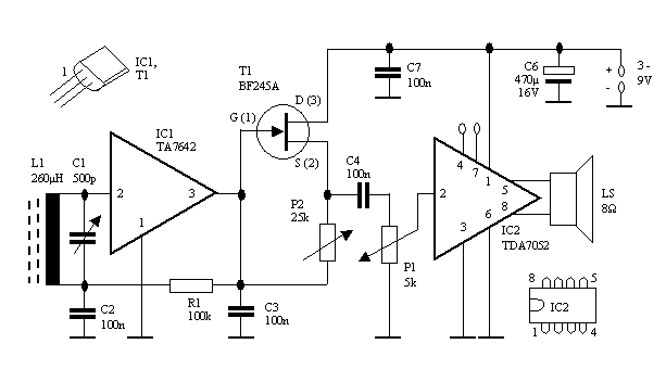
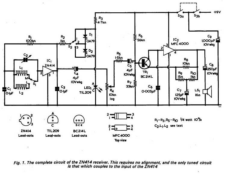
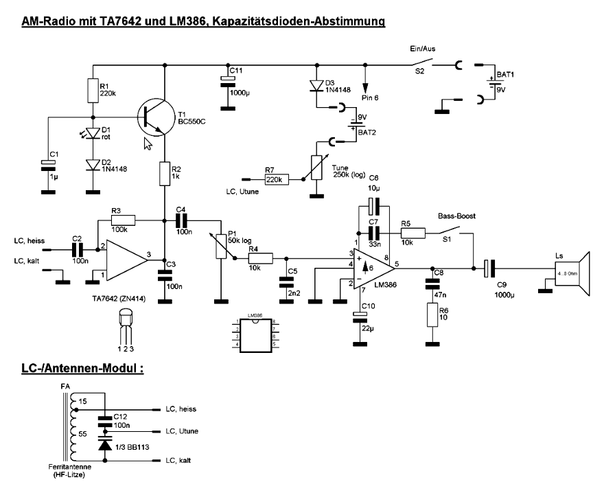
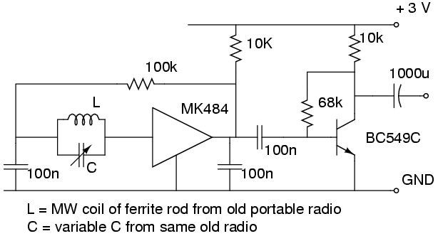
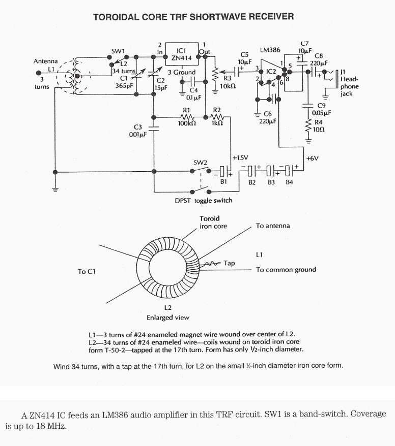
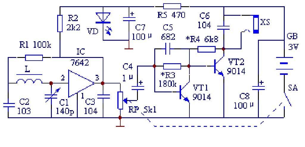
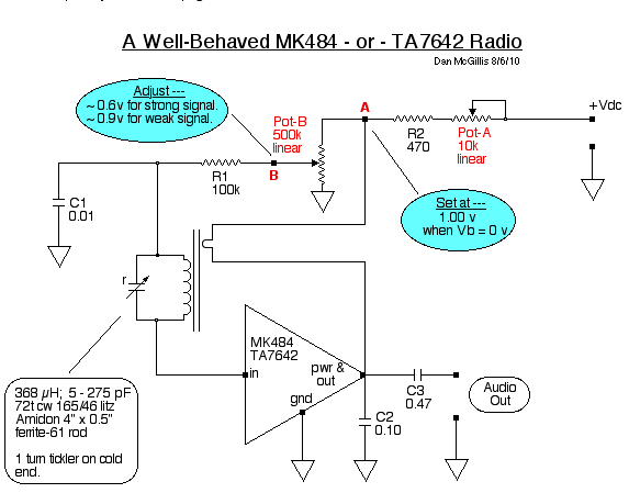
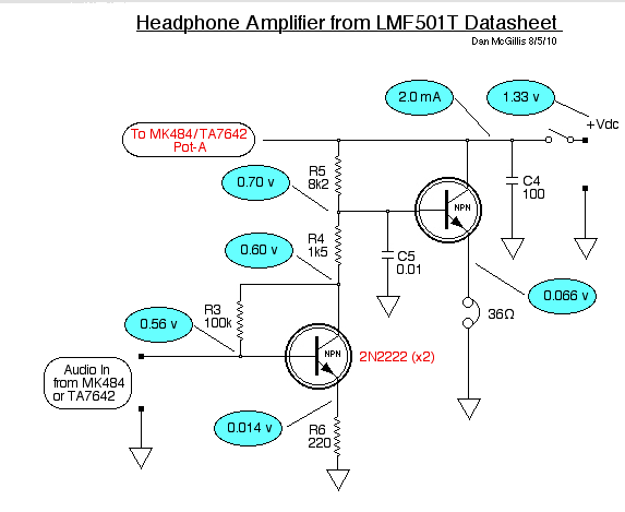
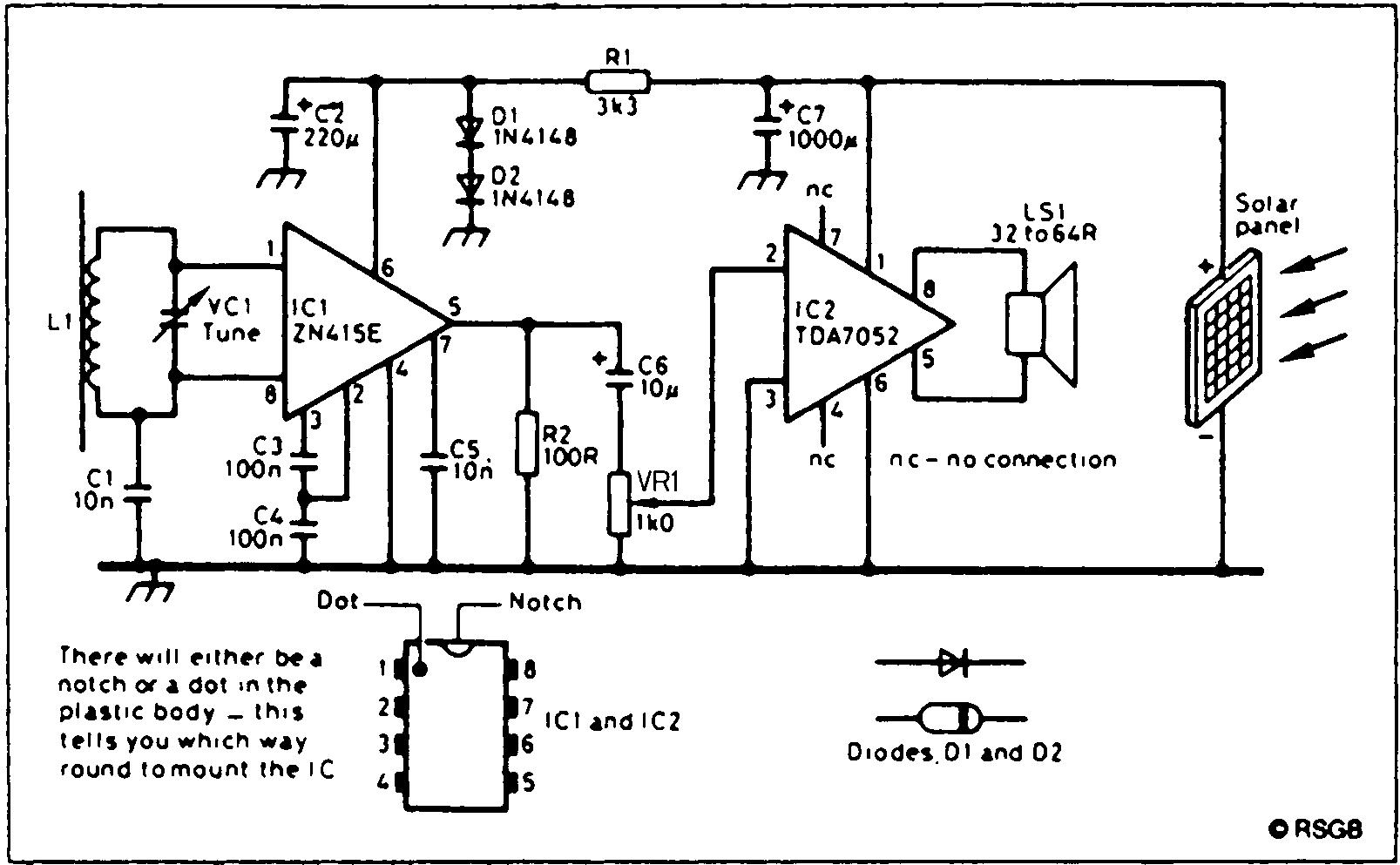
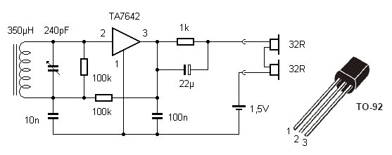
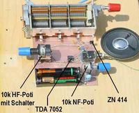
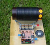
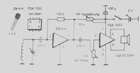
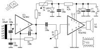
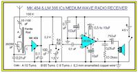
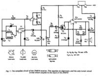
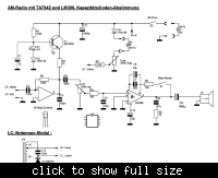
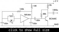
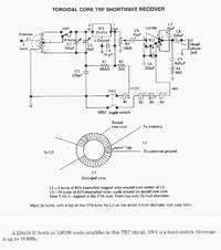
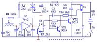
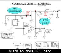
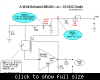
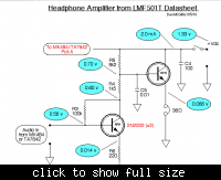
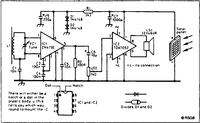
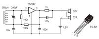
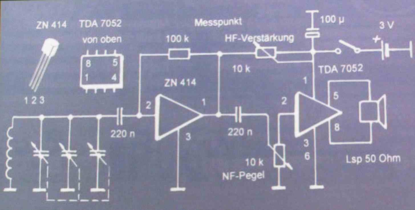
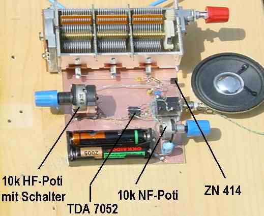
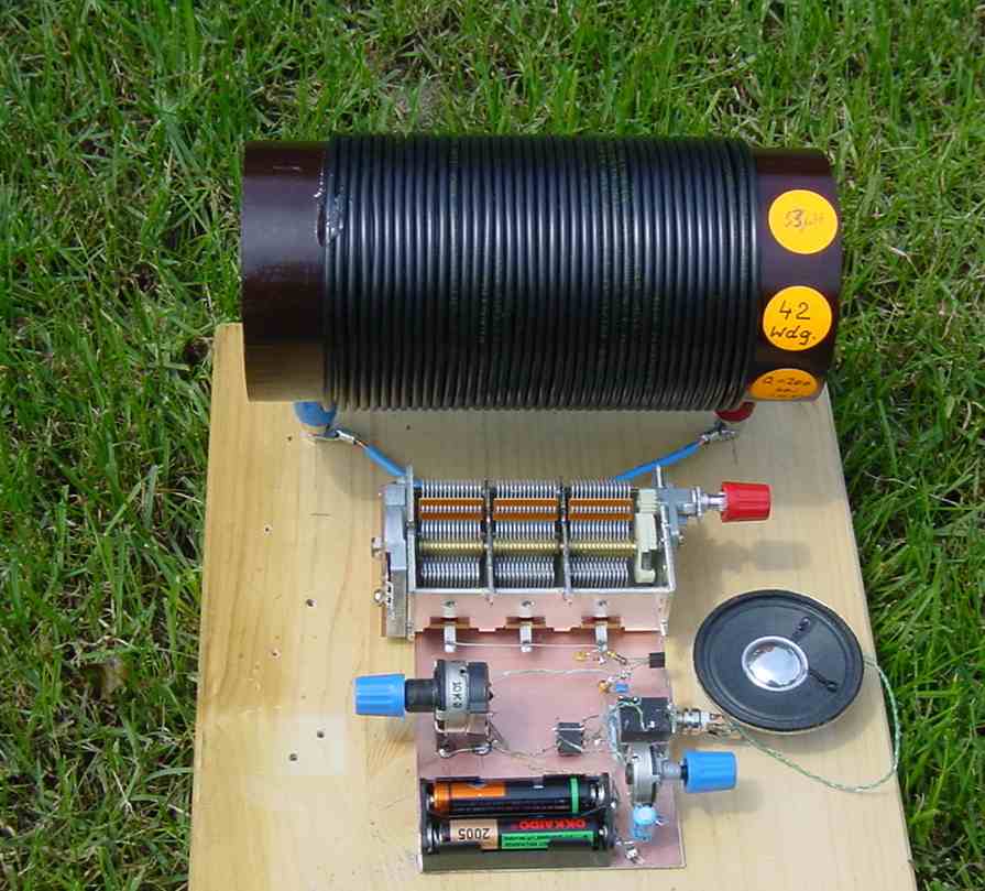
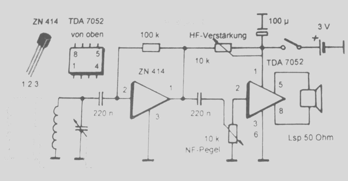
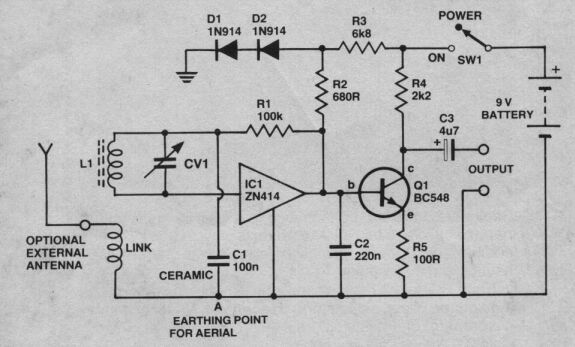
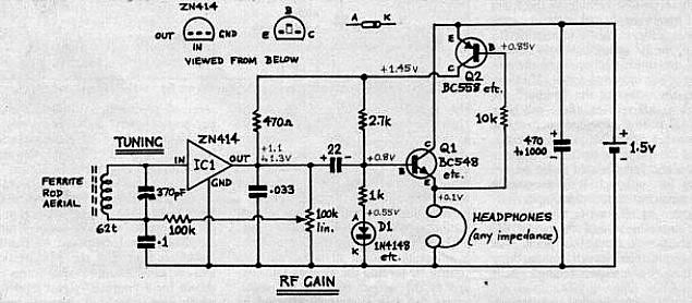
Here are presented different types of TRF radios with ZN414 and its equivalents (MK484,YS414,TA7642,UTC7642,LMF501T,LA1050) or it derivates (ZN415 and ZN416 which incorporates a small audio amplifier).

I hope them will help you and,also make your work easyer. :cool:

[url=http://obrazki.elektroda.pl/31_1333015204.png]
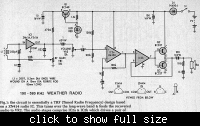
3_1333014634_thumb.jpg
[/url]
58_1333015335.gif
 

Here are the datasheets of the ICs.
 

Attachments

  • zn414_zn415_zn416.pdf
    307.1 KB · Views: 398
  • MK484 date tehnice.pdf
    426.1 KB · Views: 303
  • TA 7642 date tehnice.pdf
    664 KB · Views: 303
  • UTC7642 date tehnice.pdf
    29.8 KB · Views: 266
  • LA1050 date tehnice.pdf
    72 KB · Views: 248
  • LMF501.pdf
    61.7 KB · Views: 245
Last edited:

Other designs are presented here:
 

Attachments

  • 0302 - MK84 Shortwave Radio.pdf
    1,002.2 KB · Views: 317
  • 10376.pdf
    623.6 KB · Views: 298
  • FK708E-1.pdf
    101.9 KB · Views: 235
  • MK484AutoGain.pdf
    141.2 KB · Views: 297
  • MK484Schematic-2.pdf
    253.2 KB · Views: 311
  • MK484 Shortwave Radio.pdf
    487.4 KB · Views: 293
  • MK484 receiver.pdf
    658.6 KB · Views: 330
  • MW-LW Receiver with varactor diode.pdf
    107.2 KB · Views: 323

appreciation for your work in providing all reference in one place.
 
Thank you very much! I have made custom searchs with google.com google.de google.bg google.jp etc until now,and follow some forums and websites. Because the information sometimes is hardly to find and also "google" search is an art, I decided to make the info public, on most forums like this, like theradioboard and diyaudioprojects.

---------- Post added at 21:13 ---------- Previous post was at 20:39 ----------

NOTE: The adjustable power supply via LED and resistor/FET/bipolar transistor or just simple potentiometer is used to adjust the sensitivity of the whole receiver. In some areas are strong radiostations and this simple IC doesn't have an automatic gain controle,so we have to controle the gain manually for receiving a clear and soft sound, not a distorted one.

Two more examples are shown here:
**broken link removed**

Uploaded with ImageShack.us - for Medium Waves (the receiver covers the medium wave band band from approximately 550 to 1600 KHz)
In this circuit a small voltage regulator is built around the BC108B transistor, four 1N4148 diodes, the 2k7 and 10k preset resistor and the 820R resistor. The 10k pot acts as a selectivity control for the whole receiver, controlling the operating voltage for the ZN414 (or MK484). If you live in an area that is permeated with strong radio signals, then the voltage may need to be decreased. I found optimum performance with a supply of around 1.2 volts.

[**broken link removed**

Uploaded with ImageShack.us - for Short Waves (the receiver works well with signals up to about 6 or 7 MHz)
The 10k resistor controls the operating voltage for the IC which is critical for good performance.
The tuned circuit consists of a variable capacitor and fixed air spaced coil. For the coil, I wound between 10 and 20 turns of wire on an empty tube of around 1.5 inches diameter. The turns were spaced so that the overall length was around 3 inches. The variable capacitor tuned 0 - 300 pF but there is plenty of scope for experiment here. One final point, you will need an external antenna to receive broadcasts. I have an outside wire that is about 7 meters long and this was quite effective. The antenna can be connected at either end of the coil or via a series capacitor value between 10pF and 100pF.

Also, to understand the principle of how the MK484/TA7642 or ZN414 works (at the first post is shown also a simple schematic with 3 transistors and the points 1-2-3 which corespond to the integrated circuit pins), have a look on this diagram:
**broken link removed**

Uploaded with ImageShack.us

source: **broken link removed**

---------- Post added at 21:41 ---------- Previous post was at 21:13 ----------

Here is another radio diagram from "Radio and Electronics Cookbook" with ZN415E.

21 A portable radio for medium waves

Introduction
The ZN415E integrated circuit (IC) can be used to make a very efficient AM portable MW broadcast radio with a built-in loudspeaker. Here’s how!

The circuit
Figure 1 shows the circuit diagram of the portable radio. It’s not as complicated as it may appear, especially after you have got started. L1 is a coil of wire mounted on a ferrite rod, acting as an aerial; VC1 is a variable capacitor which works, with L1, to tune in different stations. IC1 contains circuits of its own which boost the selected signal and it includes a detector which extracts the audio signal from the incoming RF signal. Earphones could be connected to the output of IC1 (between pins 4 and 5), but the output would not be powerful enough to drive a loudspeaker.

More sound
This is where IC2, an LM386 comes in. This is a small audio power amplifier which produces audio signals with enough power to drive a small loudspeaker, LS1. The radio uses a 6 volt battery, which is made by connecting four 1.5 volt AA cells in series (4 × 1.5 V = 6 V) using a battery holder designed for this purpose. Although a 6 V supply is ideal for IC2, it is far too great for IC1, which needs only about 1.3 V. This lower voltage is provided from the 6 V supply by TR1 (an npn transistor), R2 and LED1 (a light-emitting diode). When current passes through an LED (see the description of the LED in this series) a reasonably constant voltage of 1.9 V appears between the anode and the cathode. Because of the voltage (0.6 V) that always exists between the base and emitter of a working transistor, the voltage on the emitter is about 1.9 V – 0.6 V = 1.3 V, and this is used as the power supply for IC1.

To keep the radio as simple as possible, no volume control has been fitted.Instead, you can use the directional properties of the ferrite rod aerial (see the information on ferrites in this book) to reduce the volume by rotating the set about a vertical axis using the handle provided.

Parts list

Resistors: all 0.25 watt, 5% tolerance
R1: 68 ohms
R2: 5.6 kilohms
R3: 10 ohms

Capacitors
C1, C4: 10 nanofarads (nF) or 0.01 microfarad ceramic
C2, C3, C7: 100 nanofarads (nF) or 0.1 microfarad ceramic
C5, C8, C9: 100 microfarads electrolytic,at least 10 V
C6: 10 microfarads electrolytic,at least 25 V

Semiconductors
IC1: ZN415E radio chip
IC2: LM386 audio power amplifier
LED1: 3 mm green LED
TR1: BC548 npn transistor

Additional items
LS1: Miniature 8 ohm loudspeaker
S1: Miniature SPST toggle switch
Ferrite rod Length approx. 100 mm
24 SWG enamelled copper wire (L=75 turns)

VC1: Tuning capacitor 140 to 300 picofarads (pF)
Tuning knob
8-pin DIL IC sockets (two required)
4 × AA-size battery holder (long)
PP3-type clip for battery holder
Plastic box approx. 158 × 95 × 54 mm
0.1 inch Veroboard, min. size 32 holes × 10 strips

Plus
Stranded insulated conductor for flying leads
Multicore solder
Materials for handle and speaker grille
Double-sided sticky tape or Blu-Tack
Sellotape
Glue
Four AA-size 1.5 V batteries

**broken link removed**

Uploaded with ImageShack.us
 

Hi,again! Here I'll post some new diagrams for the MK484 IC from a Russian site **broken link removed** .

**broken link removed**

Uploaded with ImageShack.us

**broken link removed**

Uploaded with ImageShack.us

**broken link removed**

Uploaded with ImageShack.us

**broken link removed**

Uploaded with ImageShack.us

And here are other designs for TA7642 and LA1050 from different sites:

**broken link removed**

Uploaded with ImageShack.us

**broken link removed**

Uploaded with ImageShack.us

**broken link removed**

Uploaded with ImageShack.us

**broken link removed**

Uploaded with ImageShack.us

For both, MW and SW here are 3 diagrams:

**broken link removed**

Uploaded with ImageShack.us
source page: http://www.vk6fh.com/vk6fh/mk484radios.htm

**broken link removed**

Uploaded with ImageShack.us

**broken link removed**

Uploaded with ImageShack.us
 

Hello everybody! I'm back again with another collection of MK484/ZN414/TA7642/LA1050/LMF501T diagrams. Have a look on them ;)

**broken link removed**

Uploaded with ImageShack.us
**broken link removed**

Uploaded with ImageShack.us
source: **broken link removed**


**broken link removed**

Uploaded with ImageShack.us
Here I think that is a 80m tuner..I don't know German. Try the website for more details: http://www.elektronik-labor.de/HF/Rx80m.html


**broken link removed**

Uploaded with ImageShack.us
source: http://www.5bcl.com/Article/Class20/200602/1278.html


KW(SW) / MW radio
**broken link removed**

Uploaded with ImageShack.us
**broken link removed**

Uploaded with ImageShack.us
source: **broken link removed**


**broken link removed**

Uploaded with ImageShack.us
source: **broken link removed**


**broken link removed**

Uploaded with ImageShack.us

**broken link removed**

Uploaded with ImageShack.us

**broken link removed**

Uploaded with ImageShack.us


**broken link removed**

Uploaded with ImageShack.us
source: http://metanest.jp/radio/la1050/la1050.html


**broken link removed**

Uploaded with ImageShack.us
source: http://www.dianlt.com/radio/2011/02099413.html http://www.dzdiy.com/html/200804/14/single-transistor-radio20080414220625.htm


**broken link removed**

Uploaded with ImageShack.us
source: http://www.felix.or.jp/Fundamentals/Make/K00907/index.html

Here is an equivalent design for the TRF IC above:
**broken link removed**

Uploaded with ImageShack.us
source: http://www.felix.or.jp/Fundamentals/Make/K00907/Darlington-K00907-Sch.jpg


Hybrid Super Heterodyne:
**broken link removed**

Uploaded with ImageShack.us
source: http://www5a.biglobe.ne.jp/jh2clv/1t2icradio.htm
 

One AM station MK484-TA7642.jpgRegenerativní přijímač LW  a MW.JPGTA7642 mit Entdämpfung.PNG

- - - Updated - - -

Hope this collection growing by contributing each of us and also help you.. There are about 50 diagrams here now.


Status
Not open for further replies.

Part and Inventory Search

Welcome to EDABoard.com

Sponsor

Back
Top