Continue to Site

Welcome to EDAboard.com

Welcome to our site! EDAboard.com is an international Electronics Discussion Forum focused on EDA software, circuits, schematics, books, theory, papers, asic, pld, 8051, DSP, Network, RF, Analog Design, PCB, Service Manuals... and a whole lot more! To participate you need to register. Registration is free. Click here to register now.

Zero crossing Issue

Status
Not open for further replies.

sajsaj220

Newbie level 5
Joined
Mar 1, 2019
Messages
8
Helped
0
Reputation
0
Reaction score
0
Trophy points
1
Activity points
95
Hi All,
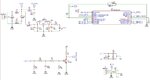
Target-PIC Mcu based IR REMOTE CONTROL To operate relay based AC LOAD. Section wise component as follows:
1) TRANSMITTER: IR REMOTE NEC protocal,
2) RECEIVER: TSOP1738,
3) ZERO CROSS: Transistor, resistor, ceramic capacitor based.
4) MCU: PIC 16F628A
5) POSER SUPPLY: TRANSFORMER 230/12V

Problems facing:
All are working correctly, but At some particular time of the day not getting output at MCU o/p pin.
If remove Zero-X, either from RB0 pin(Interrupt) or from Power i/p to zero-X Circuit from Diode-Bridge(ie, P_DC) then the ckt is working at that particular time of the day.

Why this behaves like starange?

Request Input for that issue please.

Tnx
 

Attachments

  • IR.jpg
    IR.jpg
    124.1 KB · Views: 164

At some particular time of the day not getting output at MCU o/p pin
sounds like a software problem, something that happens once per day, possibly in a timing routine or a variable overflowing.

Incidentally, 10R/100pF is not going to filter spikes from the rectified AC very well. Increase the 10R to at least 100R or increase the capacitor value or both. Beware that RC filters will introduce some phase delay but it will be constant and can be compensated in software. You might find it works better if you omit the entire P_DC to ZERO_CROSS part of the schematic and replace it with a resistor of no less than 1M and add a small-signal schottky diode from ZERO_CROSS to VDD. The signal will be inverted but probably better aligned with true zero crossing.

Brian.
 

Due to possibly distorted mains waveform, there's no guaranteed minimal width of the zero crossing pulse. In my view it's an unsuitable zc detector. I would consider to use a 50 Hz signal for the detector and trigger on both edges. By the way, what's the purpose of zero crossing detector in this circuit?
 

Tnx
betwixt:

sounds like a software problem, something that happens once per day, possibly in a timing routine or a variable overflowing.
If it is so, then why after removing the zero crossing from P_DC the ckt is start working.
replace it with a resistor of no less than 1M and add a small-signal schottky diode from ZERO_CROSS to VDD.
Are you asking a 1M resistor directly from LIVE to INT pin and a small-signal schottky diode (ie, 1N4148) from VDD to INT pin.- if wrong correct please....

Also Tnx
FvM
Due to possibly distorted mains waveform,
I think so.
minimal width of the zero crossing pulse
Could you plaese refer a ckt for minimul width.

Tnx all of you.
 

If it is so, then why after removing the zero crossing from P_DC the ckt is start working.
Without knowing what the zero crossing signal does in your software it is impossible to answer that.
Are you asking a 1M resistor directly from LIVE to INT pin and a small-signal schottky diode (ie, 1N4148) from VDD to INT pin.- if wrong correct please....
What I mean is link the signal called 'P_DC' to the 'ZERO_CROSS' via a 1M resistor. The resistor will limit the current to a safe level that allows the pin internal protection to keep it within safe limits. Adding the diode will give even better protection, a schottky diode will clamp the voltage better than the internal diode. Note that a 1N4148 is not a schottky device!

Brian.
 

Status
Not open for further replies.

Similar threads

Part and Inventory Search

Welcome to EDABoard.com

Sponsor

Back
Top