Continue to Site

Welcome to EDAboard.com

Welcome to our site! EDAboard.com is an international Electronics Discussion Forum focused on EDA software, circuits, schematics, books, theory, papers, asic, pld, 8051, DSP, Network, RF, Analog Design, PCB, Service Manuals... and a whole lot more! To participate you need to register. Registration is free. Click here to register now.

Zero Crossing Detector

Status
Not open for further replies.

alex051

Newbie level 5
Joined
Apr 20, 2010
Messages
10
Helped
0
Reputation
0
Reaction score
0
Trophy points
1,281
Activity points
1,389
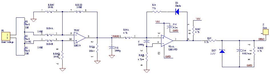
I am trying to implement a Zero Crossing detector to generate square wave from the grid AC voltage to apply it in an inverter.

Does anyone has any suggestion how to do that?

Thanks
 

Have a look at the attached drawing ..
This zero-crossing detector is simple and safe, as the voltage is fed through step-down transformer ..
It's not the only way of detecting zero-crossing, but as I mentioned above, it's probably one of the simplest concepts ..

Rgds,
IanP
:|
 

Thanks IanP.

Do I have to use the transformer? If I couldnt get the transformer is it ok if I use just a resistive voltage divider to reduce the grid voltage to 9V?
 

You can achieve similar results without transformer, but it's without any isolation, so be aware of that issue ..

Attached is an interesting variation of similar circuit that generates very short pulses at zero-cross and in the same time Q2 BE-junction provides reverse-polarity protection to the base of Q1 ..

Rgds,
IanP
:|
 

Actually, if you want to generate signals synchronised with mains, you should use a resistive divider instead of a transformer. Transformer's inductance may introduce a delay, a phase shift. Methinks.
If I'm wrong, correct me.

JS.
 

You can use an optocoupler to achieve isolation, like this **broken link removed**
 

I did a search on EDN to find the original article of the figure that 'pauloynski' gave a URL above. See page 2 of this PDF.

**broken link removed**
 

I am using the following circuit as zero crossing detector to get a square wave from the grid voltage.

But the disturbance coming from the switching current is interfering with the circuit and the square wave is distorted as I increase the input power to the inverter. any ideas how to fix that?

Thanks


I see two points:
- It's unclear, how the circuit ground is referenced to the mains voltage. The differential amplifier must be expected to show limited common mode rejection, particularly for higher frequency interferences.
- If you operate the inverter grid connected (the purpose of the zero crossing detector isn't excatly clear, but the description sounds
like intending inverter mains synchronisation), the mains waveform may actually affected by by non-sinoidal currents, depending on the
mains impedance. Utility companies usally require a high power factor for grid connected inverters.

What do you mean by the mains impedance? Is that grid impedance?

The ground of the zero crossing circuit is connected to one terminal of the grid voltage.

The zero crossing detector is used to synchronize the positive and negative half cycle PWM signals.

The inverter is supposed to injected current of unity power factor into the grid. And the zero crossing detector output is supposed to be a square voltage of 60Hz. And when the square wave is 1 the high side MOSFET is switched and when the square wave is 0 the low side MOSFET is turned on.

But what happens is when I increase the dc voltage input to the inverter a high frequency noise is superimposed on the sinusoidal input of the Zero Crossing Detector circuit and the square wave is distorted, which affects the PWM signals. And sometimes the wrong MOSFET is switched and current flows from the grid to the inverter burning the MOSFET.
 

Yes, I was referring to grid impedance. Wheter it's a problem of inductive grid impedance or not, your detail desription basically clarified the problem. I think, you have to filter the input to the zero crossing detector to suppress PWM intereferences. A low pass should be sufficient normally, there's a problem of involved phase shift however. One possible solution is a bandpass (may be low Q) with the center at the mains frequency, that will generate zero phase shift.

Not directly related to the problem, but I don't exactly understand the inverter operation principle. Unity power factor would imply a sine PWM. You tell however:
And when the square wave is 1 the high side MOSFET is switched and when the square wave is 0 the low side MOSFET is turned on.
But a grid connected sine PWM would require the sine generator synchronized to the grid, not just switching a polarity.
 

Thanks FvM.

The inverter output is sine wave. And I am using sinusoidal PWM to drive the MOSFETs. But what I meant to say is I select which PWM module to operate and which one to shut down depending on whether the square wave is 1 or 0.

Do you have any suggestion for bandpass filter circuit? Or any links?
 

You can design a 2nd order bandpass with Texas Instruments FilterPro Software. Choose a bandwidth of e.g. 20 - 50 Hz. If the phase error is critical, you can provide a variable resistor for fine tuning.
 

Hello. I have the following question

In case of a three-phase inverter. Do I need to use three zero-crossing detectors for each phase or is it enough to use one and detect the zero-crossing of any phase (no matter which one) ?

And one more thing:

Ultimately - is a transformer based zero-crossing detection circuit a problem for such application because of the delay or not ?

Thanks in advance.
 

An ideal grid connected inverter should supply a sinoidal current (respectively a three phase current system) in phase with the grid
fundamental voltage. Real inverters are rather voltage sources with finite impedance than ideal current sources, so the performance
can be typically improved, if the inverter output follows the actual grid voltage (respectively three phase system).

In the first case, a single phase zero crossing detector would be sufficient to control the inverter's internal reference generator,
in the latter, two interphase voltages would be measured as analog quantities and processed by the inverter controller.

A measurement transformer can be expected to have a phase error, but other functional blocks of the inverter add errors, too. An overall phase adjustment for maximal power factor should be provided by the inverter controller.
 

Thank you very much. It is not a real thing that I am going to build but still:

I am wondering:

Let's say we are measuring the interphase voltages in a 0.4 kV utility.

The inverter controller works with signals <3V so in order to process the signal with the controller I need to use step-down transformer.

1. I was thinking of using a step-down transformer 220 V to let's say 24 V and then use resistive voltage divider to lower 24 to 3Vmax. This means two transformers and two voltage dividers only for the zero-crossing detection. Or would you suggest something else ?

2. You may be wondering why I am thinking of using both transformer and voltage divider - the transformer will consume less power than the divider or am I wrong again?

3. If monitoring one phase is not enough - why monitoring 2 instead of all 3 phases ? Could you please explain that to me in a more detailed way.

Thanks.
 

2. You may be wondering why I am thinking of using both transformer and voltage divider - the transformer will consume less power than the divider or am I wrong again?

If you use very high resistors like I am using 2M and 16.9K then the resistive voltage divider will not consume power.

3. If monitoring one phase is not enough - why monitoring 2 instead of all 3 phases ? Could you please explain that to me in a more detailed way.

I think for synchronization detecting 2 phases is enough because once you determine the phase sequence of two of the three phases the third one is easy to figure out because the phases are 120 degrees apart from each other.
 

why monitoring 2 instead of all 3 phases
The third voltage is either the sum or difference (depending on your polarity definition). Of course this applies to the sine waveform, not the sign signal. so you still need three zero crossing detectors, if you want to sense the three voltage signs. If you only want the three intervoltage voltage signs (with isolation), optocouplers are actually the most simple solution.

At least two phases should be monitored to sense the phase sequence.

As I already said, zero crossing detection allone is probably not sufficient to operate a grid connected inverter.
 

FvM said:
As I already said, zero crossing detection allone is probably not sufficient to operate a grid connected inverter.

Well, what else does it need? A way to measure the grid voltage I guess...
 

Status
Not open for further replies.

Similar threads

Part and Inventory Search

Welcome to EDABoard.com

Sponsor

Back
Top