Continue to Site

Welcome to EDAboard.com

Welcome to our site! EDAboard.com is an international Electronics Discussion Forum focused on EDA software, circuits, schematics, books, theory, papers, asic, pld, 8051, DSP, Network, RF, Analog Design, PCB, Service Manuals... and a whole lot more! To participate you need to register. Registration is free. Click here to register now.

Zero Crossing Detector Circuit Simulation

Status
Not open for further replies.

noobeestudent

Member level 1
Joined
Jul 4, 2019
Messages
37
Helped
0
Reputation
0
Reaction score
0
Trophy points
6
Activity points
290
Hey, I need help with my assignment. I was required too build a Phase Firing Circuit for a aquarium heater that I am going to use in a PCB Etching Tank.

I've finalized the design for the Phase Firing Circuit and now I need help in designing the Zero Crossing Circuit.
For the Zero Crossing Circuit, I am using a 4n25 Optocoupler to detect the zero crossing point.

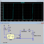
1591519140307.png


This is my initial design. The green trace represents the AC while the blue trace is the voltage measured across the resistor R1.
Although simulation is working, it seems that the 4N25 should not be able to support the voltage supplied.


Thus, I have added a current limiting resistor of value 1MΩ after the bridge rectifier. However, doing that decreases the voltage of the resistor R1.
This might caused a few errors as my PIC might not be able to detect it.
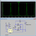
1591520049402.png

From the simulation, the voltage drop across R1 is observed to drop significantly.

I am currently stuck and not sure what I should do to overcome this problem. Please help and provide suggestions.

Below attached is the simulation circuit file.
 

Attachments

  • Zero Crossing Circuit.zip
    661 bytes · Views: 75

Electronic design is a bit more than arbitrarily dropping components on a schematic sheet.

How did you calculate the 1 Mohm resistor value? 4N25 has a specified minimal transfer ratio of 20%, thus you need to drive at least 5 mA to the LED to turn the transistor fully on in your circuit.. It may be a good idea to increase the collector load resistor.

Another point is that 1N4148 can't stand mains voltage. You want change the current limiting resistor position or use high voltage rectifier diodes.
 

You'll notice that the output signal isn't very sharp. The simple circuit might miss your timing accuracy requirements.

ZC.PNG
 

I have forget to mention that the diodes were simply chosen to form a bridge rectifier for simulation.

You'll notice that the output signal isn't very sharp. The simple circuit might miss your timing accuracy requirements.

View attachment 162070

Do you have any suggestions to improve the output signal?
 

The output should be connected to an I/O pin of a PIC16F887 microcontroller. After that, I,'ll use a delay function before sending out a pulse to the Phase Firing circuit.
 

Hi,

Designing electronics does not mean to choose random values.
They should be calculated. No need for an exact calculation, maybe no need for a calculator at all..but at least a raw estimation.
In your case..follow these steps:
1) it's just ohm's law (multiply / divide) for the optocoupler input side.
You know your input voltage, and the datasheet says the max allowed current. Now you are free to decide how much you want to go below this maximum. A good hint is the "recommended operation condition" or the "test conditions" given in the datasheet.

2) ..now you know the input current ... and waveform.
Thus you can use the CTR of the datasheet and calculate the expected output current ...and waveform.

3) now you know the output current ...but you want "output voltage".
So again use ohm's law to calculate the value of the pullup resistor. Decide at which point of time you can expect which current ...and what voltage you expect. I, V -->R

And this is what we professionals need to do, too. But it becomes faster ... with increasing practice and experience. You will become faster, too.

Klaus
 
Last edited:

I'd try a slightly different concept. Can use PIC input change notification which is sensitive for both edges. LED current and load resistor can be adjusted for almost symmetrical delay. High voltage rectifier diode is optional, reducing resistor power dissipation.

1591526384846.png
 

Knowing that I need 5mA of current supplied to the LED of the I chose a resistance value of around 60kΩ. However, using around 60kV, i have noticed problems

This is the simulation that I have ran. I intend to use connect the TEST Point of the Circuit directly to an interrupt bit of a PIC Microcontroller.
1591624726061.png


  1. The power dissipated by the Resistor R2 is quite high(around 1.9Wpeak) as shown in The first plot plane.
  2. The voltage at the TEST point is not very sharp. Thus, the interrupt of microcontroller might trigger as soon as the TEST point reaches about 3V or 4V. This might cause the phase firing to be incorrect.
Do you guys have any suggestions on how to overcome the problem I Have mentioned? Please Help me.
 

I have since replace the 1kΩ Pull-up resistor with a 10kΩ resistor and the signal became sharper.

However, i am still facing the first problem as mentioned above (About the power rating of the resistor). Do you guys have any suggestion to overcome the issue?


Knowing that I need 5mA of current supplied to the LED of the I chose a resistance value of around 60kΩ. However, using around 60kV, i have noticed problems

This is the simulation that I have ran. I intend to use connect the TEST Point of the Circuit directly to an interrupt bit of a PIC Microcontroller.
View attachment 162087

  1. The power dissipated by the Resistor R2 is quite high(around 1.9Wpeak) as shown in The first plot plane.
  2. The voltage at the TEST point is not very sharp. Thus, the interrupt of microcontroller might trigger as soon as the TEST point reaches about 3V or 4V. This might cause the phase firing to be incorrect.
Do you guys have any suggestions on how to overcome the problem I Have mentioned? Please Help me.
 

To sharpen the signal transitions, you must use a schmitt trigger. The CD4093 or CD40106 are common ICs.

To lower the primary current, use a high-CTR optocoupler, like the photodarlington FOD8523SD.
 
Last edited:

I'd try a slightly different concept. Can use PIC input change notification which is sensitive for both edges. LED current and load resistor can be adjusted for almost symmetrical delay. High voltage rectifier diode is optional, reducing resistor power dissipation.

View attachment 162071
I am also looking into this circuit. This will require me to use a Change-on-interrupt method on my PIC.

On a side note, this might be a stupid question but, does the Power Rating of a resistor refer to the RMS power or Peak Power across the resistor?
 

Hi,

1) the average power is below 1W. You are free to use any oher value. How did you calculate it?

2) we already gave two oprions:
* either go on with points 2) and 3) of post#7..
* or use the schematic / part values of post#8

Klaus
 

To sharpen the signal transitions, you must use a schmitt trigger. The CD4093 or CD40106 are common ICs.
I have already tried and have managed to solve the issue. By changing the resistance of the Pull-up resistor, the signal have since become much sharper

1591628507473.png
 

To lower the primary current, use a high-CTR optocoupler, like the photodarlington FOD8523SD
 

Hi,

the Power Rating of a resistor refer to the RMS power or Peak Power across the resistor?
The datasheet should be unambiguous in this.
You need to see the SOA chart and you need to be sure that you keep on PCB layout recommendations to spread the heat. Also you need to ensure ambient temperature and air flow to be in the specified range.

My recommendation: Don´t go to the limit. I try to keep part temperatures low, thus often I use parts with 500% rated power dissipation. Not always.
It mainly depends on how long the part is powered. But in your case the resistor may be powered 100% 24/7...

Klaus
 

Hi,


The datasheet should be unambiguous in this.
You need to see the SOA chart and you need to be sure that you keep on PCB layout recommendations to spread the heat. Also you need to ensure ambient temperature and air flow to be in the specified range.

My recommendation: Don´t go to the limit. I try to keep part temperatures low, thus often I use parts with 500% rated power dissipation. Not always.
It mainly depends on how long the part is powered. But in your case the resistor may be powered 100% 24/7...

Klaus
I am using normal Carbon film Resistors and I have found this datasheet.

In the datasheet, this was found.
1591629944004.png


Does that mean that the power rating is based on average power? I am still not very sure about the power ratings.
 

Hi,

It depends.

for sure - if the pulse frequency is high enough - the resistor just need to spread the heat (power, average power).
(= pure heat spreading)

But if you have short high pulses the resistor need to "store" some pulse energy and dissipate it inbetween two pulses.
(heat storage, similar as a capacitor stores electrical energy. ...and heat spreading)

See the "single pulse power" chart. for 10ms the resistor can dissipate around 20W !!! (but it needs long time to cool down before it can get the next pulse) while on DC load it can dissipate only 1W
On a 10us pulse it can even widthstand 570W.

The resistor can not withstand more than 1W. For pulsed load it is always less. And for your rectified 50Hz pulses you need to reduce it so it can overheat for about 5ms and can cool down while the other 5ms.

Now look at the Power Derating Curve. it ends at 155°C. You may expect that this is the maximum allowed chip temperature ... and it is likely to meet this temperature all over the derating area.
For a raw chip temperature estimation at 20°C ambient temperature and 1W you get about 105°C. Do you want it to get that hot?
Mind: your fingers can´t stand even 50°C for a longer time!

Klaus

added: I just noticed that in post#12 you talked about "RMS power".
---> There is no such thing as "RMS power".
 

Hi,

Does that mean that the power rating is based on average power? I am still not very sure about the power ratings.

I thought resistor power ratings are based on DC and 100% is usually only to 70°C, and it's all downhill from there.

Although specifically about inductors, Coilcraft document 361-1 'Current and Temperature Ratings' has a good conversion chart at the end: 'Appendix C - Conversion Factors for Various Waveforms'. You might find it interesting.
 

...and put the resistor on the AC side of the bridge rectifier. It makes no practical difference to the operation but you can use much lower voltage rated diodes in the bridge. Even 1N4148 can be used because the LED in the optocoupler will clamp the maximum voltage across them.

Brian.
 

Status
Not open for further replies.

Similar threads

Part and Inventory Search

Welcome to EDABoard.com

Sponsor

Back
Top