Welcome to our site! EDAboard.com is an international Electronics Discussion Forum focused on EDA software, circuits, schematics, books, theory, papers, asic, pld, 8051, DSP, Network, RF, Analog Design, PCB, Service Manuals... and a whole lot more! To participate you need to register. Registration is free. Click here to register now.
hello.. i just to know.. what the effect if we use the HIgh Zo (e.p 80Ω) and Low Zo (30Ω) in designing impedance matching network.? that have effect of performance?.
I may be able to help you if you define the problem more clearly. Are u trying to match a 50 ohm system to some impedance or you want to design a whole system based on 80 or 30 ohms?
Maybe this is referring to using offset sections of either 30Ω or 80Ω microstrip (or coax) when designing a matching section.
eg in a 50Ω system you can match a complex load (one that has reasonable return loss already) by placing a specific length of 80Ω (or other higher than 50Ω impedance) line at a specific distance (made up from 50Ω microstrip) from the load.
You can do exactly the same with 30Ω line but the dimensions/distances will be different.
A high Z line will be thinner so might suffer with thermal management issues and a low Z line will be fatter and will need more PCB space. Also, if you are running up at many GHz you can run into problems with the upper frequency limit for the microstrip section.
I wrote a design program for this matching method about 15 years ago as it can be useful for matching high power 50Ω antennas using lengths of 75Ω coax that give minimal loss and high power handling.
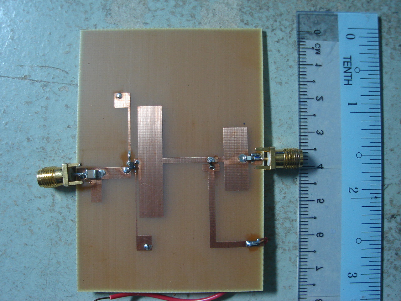
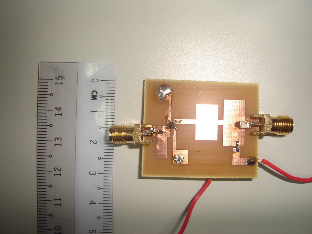
actually now i try to design the Class-E and Class-F power amplifier at 2.4GHz and 5.8GHz.. but this project no give a good result..
so i just want to know that if Z high and low can effect the performance..
for input matching i use Zo=50Ω..but ad output matching i use Zh=80 for inductance device and Zo=30Ω for capacitance..
Maybe I'm missing something but I don't see a ground plane on the top side, are you SMA's connected to GND on the bottom layer? I think people would be able to be of more help if you provided a schematic, and a pic of the underside of the board
This site uses cookies to help personalise content, tailor your experience and to keep you logged in if you register.
By continuing to use this site, you are consenting to our use of cookies.