Continue to Site

Welcome to EDAboard.com

Welcome to our site! EDAboard.com is an international Electronics Discussion Forum focused on EDA software, circuits, schematics, books, theory, papers, asic, pld, 8051, DSP, Network, RF, Analog Design, PCB, Service Manuals... and a whole lot more! To participate you need to register. Registration is free. Click here to register now.

Yamaha RX-V657 AV Receiver Not Turning On

Status
Not open for further replies.

Zaccoh

Newbie level 6
Joined
Apr 22, 2020
Messages
11
Helped
0
Reputation
0
Reaction score
0
Trophy points
1
Activity points
91
Hi all, hope everyone is safe and well.
I have been trying to troubleshoot the power supply circuit on my yamaha amp, I replaced the capacitor c405 as I read it was a common issue with the rxv models but it still won't turn on. I'm getting 240vac at the supply and at the ac outlet, 180mv ac at cb402, similar reading at d405 and 0.36vdc across pins 14 and 7 of the IC.
Can anyone shed some light on what might be the issue? I'm a sparky by trade but have almost no experience with electronics, I read a similar post here and was hoping someone might have more of an idea than me.
Cheers.
 

Do you have a schematic, maybe from a service manual?
 

Hi Stenzer, thanks for your reply, I do have one that I got from another thread actually but I cannot see the option to attach it here, perhaps because I am on my mobile :/
It's almost 11 30 pm here, I'll have to try again tomorrow. I'll upload it asap.
 

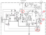
yamaha.JPG

Please not that the values in red are not relevant to my receiver, this schematic was taken from another thread about the same model receiver.
 

According to your first post, VHIS and CB407 are your AC mains input. VHIS and CB407 and are connected to VSHI and CB402 in the upper middle connector shown in your circuit. As you are measuring an AC voltage in the milli volt range at CB402 I would check the fuses F1 and F2 first, maybe even the connectivity of your switch, if you haven't already.

Unplug the 230 V mains!!!! Wait for a sufficient time to allow a discharge of all capacitors at the mains side. Do not touch them at their leaded spots, as they can contain large amount of energy! Use the lowest resistance measuring range of your multimeter and check the resistance of F1, F2 and your mains switch (RY401 ?) when turned on. They all should be in the ~1 Ω range.

I don't know what TE401 / s9 is, maybe a surge protection / MOV. Could you attache an image, showing this component?

Greets
 

Be very careful taking voltage measurements. This is an unusual supply arrangement, the MOSFET Q404 is the mains switch!

The whole section of schematic between the power cable and the two optocouplers is 'floating' so any voltage measurements to the chassis are not valid. If the voltage measured directly between pins VSS and VDD of the IC is only 0.36V it will not function. The supply comes via C405, R419 and D406. The most likely cause of the problem is C405 going open circuit, next guess would be C406 going open circuit so the IC is trying to run on a pulsed supply.

Brian.
 
  • Like
Reactions: stenzer

    stenzer

    Points: 2
    Helpful Answer Positive Rating
According to your first post, VHIS and CB407 are your AC mains input. VHIS and CB407 and are connected to VSHI and CB402 in the upper middle connector shown in your circuit. As you are measuring an AC voltage in the milli volt range at CB402 I would check the fuses F1 and F2 first, maybe even the connectivity of your switch, if you haven't already.

Unplug the 230 V mains!!!! Wait for a sufficient time to allow a discharge of all capacitors at the mains side. Do not touch them at their leaded spots, as they can contain large amount of energy! Use the lowest resistance measuring range of your multimeter and check the resistance of F1, F2 and your mains switch (RY401 ?) when turned on. They all should be in the ~1 Ω range.

I don't know what TE401 / s9 is, maybe a surge protection / MOV. Could you attache an image, showing this component?

Greets
TE 401 is the AC outlet at the back of the amp, F2 is not and has never been populated, it's just blank and the relay RY401 is not turning on.

I appreciate your help Stenzer, cheers.
 

Be very careful taking voltage measurements. This is an unusual supply arrangement, the MOSFET Q404 is the mains switch!

The whole section of schematic between the power cable and the two optocouplers is 'floating' so any voltage measurements to the chassis are not valid. If the voltage measured directly between pins VSS and VDD of the IC is only 0.36V it will not function. The supply comes via C405, R419 and D406. The most likely cause of the problem is C405 going open circuit, next guess would be C406 going open circuit so the IC is trying to run on a pulsed supply.

Brian.

Interesting circuitry, I never seen such a topology until now. Brian thank you for explaining it :thumbsup:. Do you know what TE401 / s9 is, I don't know the "symbol"?
 

Hi Betwixt, I appreciate you're involvement, 3 heads are better than one eh.

I replaced C405 already and it seems to be accepting it's charge, I just checked it again with the meter, C406 gives me a flat reading of 427.7 k ohms, a high reading such as this represents an open cct correct? My apologies, feel like such a newb haha, but I think you're on to something here.
 

I soldered in a new capacitor this morning and it seems that the new one has gone open circuit now as well??
Any ideas?
I've been looking at this thing for over a week and I'm determined to repair it, I was given a record player for my 31st birthday and I want to play my late fathers records using his amp (this amp) haha so, I'll get there eventually.
Cheers,
Zac
 

I soldered in a new capacitor this morning and it seems that the new one has gone open circuit now as well??

Are you saying it has high ohmic resistance?

Or do you mean short circuit?

You can check a capacitor's condition with an ordinary meter. (First measure its charge. Drain until it's no more than 1 or 2 V.)

[Edited to add: the capacitor must be out of circuit.]

Set ohmmeter high range setting. Connect leads to cap, watch meter show low ohms at first, then rise to high ohms. Reverse leads and it does the same thing. Action takes a second or two with thousands of uF. A brief fraction of a second with small value.
 
Last edited:

Hi,

which capacitor have you changed, C406? As you mentioned you have almost no expierence with electronics, have you but it in the right way? C406 is an electrolytic capacitor with a deticated + and - pole. But usually you smell/see it if you blow up an electrolytic capacitor :lol:. Also the capacitor's voltage rating is critical. I have not found a datasheet for D405, but the TC4013BP can be operated with a supply voltage Vdd up to 20 V. So the capacitor should have a larger rating than the actual Vdd.

Greets
 

Are you saying it has high ohmic resistance?

Or do you mean short circuit?

You can check a capacitor's condition with an ordinary meter. (First measure its charge. Drain until it's no more than 1 or 2 V.)
Set ohmmeter high range setting. Connect leads to cap, watch meter show low ohms at first, then rise to high ohms. Reverse leads and it does the same thing. Action takes a second or two with thousands of uF. A brief fraction of a second with small value.

Hi Brad, thank you as well for jumping in, I need the help haha.

Yeh it's showing a high resistance, 427 k ohms, but I tested it before I soldered it in and it was fine.

- - - Updated - - -

Yeh the polarity was correct, I made sure it was the same as the one I pulled out, it definitely didn't blow, the original was rated at 50v and the new ones I purchased have the same 1uF rating but a voltage rating of 60v.

Cheers
 

Note that capacitors should have a very high resistance, at least after they have charged so measuring with a normal meter doesn't really tell you anything. You need a capacitance meter to give reliable results. 427K may be a good reading, what you see will depend greatly on the meter you use but it isn't an unreasonable value.

I have an RX-V365 which I think has a similar PSU but I've never opened it up to see.

Note that C405 must be a NON-poarized capacitor, not an electrolytic.
With the power cord disconnected and after a few minutes to let everything discharge, try measuring the resistance across D405 and again across C405 with them in place on the board. Take two measurements of each, one with meter probes reversed then tell us what you find.


Brian.
 

Hi again Brian, so I replaced C405 with more or less an exact model of the original, green cap with the same ratings.
I took the readings that you asked and the results are as follows:

C405- starts from low resistance and consistently increases
With probes reversed- jumps from low resistance to OL.

D405- starts from low resistance and consistently increases.
With probes reversed- jumps to 580.0kohms

Cheers,
Zac
 

Hi,

C405: sounds as it is charged by the multimeter.
D405: If it is still mounted on the board the capacitor C406 is charged for the first measurement as D406 is conductive and D405 not. Second measurement D405 is conductive, and D406 is not thus a a constant high resistance is measured.

So far it sounds OK for me, but maybe Brain has a different opinion.

Greets
 

For a symptom like: No voltage output when power-up but fuse not blown, no abnormal sound, no blowing semiconductor (transistor, diode, etc).
Possible root cause are:
Defective start up resistor
Bad inrush current limter resistor
Defective PWM IC
Defective feedback/control components (like opto)
Bad capacitors (mostly electrolytic)
High frequency transformer open

General repair tips here --> https://elex518.blogspot.com/
 

Hi everyone, hi i200yrs, sorry for the late reply and thanks for your input, I had to fly up north to do some work on my brothers property and will return around june to continue troubleshooting the receiver.
I will get post again once I have applied some of the above ^^.
Cheers, take care all.
Zac.
 

Hi everyone, I hope you're all still safe and well. I have returned and have still not solved the receiver issue, so yes I still need your help if you're willing, could it be IC 402 or mosfet Q404? Or am I in over my head here? I'd really like to get it up and running. I appreciate your help, thanks,
Zac.
 

I'm pretty sure it's the Q404. That's what was broken on my exact same amplifier. Changed it to STD2HNK60Z-1 power transistor which can handle more power and the amp has worked flawlessly ever since.
 

Status
Not open for further replies.

Part and Inventory Search

Welcome to EDABoard.com

Sponsor

Back
Top