Continue to Site

Welcome to EDAboard.com

Welcome to our site! EDAboard.com is an international Electronics Discussion Forum focused on EDA software, circuits, schematics, books, theory, papers, asic, pld, 8051, DSP, Network, RF, Analog Design, PCB, Service Manuals... and a whole lot more! To participate you need to register. Registration is free. Click here to register now.

XOR gate using only two 2-to-1 muxes?

Status
Not open for further replies.

mrcabnit

Newbie level 1
Joined
Oct 12, 2010
Messages
1
Helped
0
Reputation
0
Reaction score
0
Trophy points
1,281
Activity points
1,293
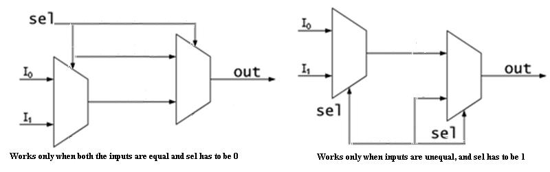
Is it possible to create a XOR gate using two 2-to-1 mux's if you do not have access to A bar or B bar and can not use an inverter or not gate. I think it is impossible, but my professor is convinced otherwise. If A and B are both 1 it seems that it would be impossible to make the output 0 using only a select line, regardless of how many mux's you can use. The only way I can figure out how to do it but it requires opening up the mux and rewiring it, and then it is obviously no longer a multiplexer.
 

Yes, it is not possible to implement a XOR gate without using any inverters. But I think you need two different circuits as shown in the attached figure (though that's not what your prof want)


Of course it's possible. Consider that a mux can also act as an inverter. The number of possible logic circuits with two muxes is limited, you can afford to try them systematically.
 

Hi FvM,
It is possible to implement XOR gate using only two 2-to-1 muxes, I tried a lot of configurations, but couldn't figure out.
 

It is possible.. and is very simple actually Take a look at the image if you can get the idea. It is made on the quartus and is not well done hehe.


The inputs are the sel signals. lets say the mux connected to the output is the MUX2 and the other one is the MUX1. And the input connected sel of to MUX2 of B and the other of A. If B is 0, the output is A, so if A is 0 the output is 0 and if A is 1 the output is 1. If B is 1. The output is selected by A signal. If A is 0 the output is 1 if A is 1 the output is 0. We got a XOR
 

Attachments

  • XOR.JPG
    XOR.JPG
    67.5 KB · Views: 278
Last edited:
And I was soooo close. The trick was to broaden my approach to redefine the Sel lines as inputs... I was one input off (on MUX1; didn't see it solely as an inverter) I didn't see the implications of FvM's observation soon enough.
 

Hahaha sorry for giving the solution, i should have let this for you... i dont know id there is a better solution but this one was the one that came to me ...


Good luck!!
 

Status
Not open for further replies.

Part and Inventory Search

Welcome to EDABoard.com

Sponsor

Back
Top