Continue to Site

Welcome to EDAboard.com

Welcome to our site! EDAboard.com is an international Electronics Discussion Forum focused on EDA software, circuits, schematics, books, theory, papers, asic, pld, 8051, DSP, Network, RF, Analog Design, PCB, Service Manuals... and a whole lot more! To participate you need to register. Registration is free. Click here to register now.

xilinx FIR core problem

Status
Not open for further replies.

arash rezaee

Member level 5
Joined
Sep 10, 2009
Messages
87
Helped
0
Reputation
0
Reaction score
0
Trophy points
1,286
Activity points
1,952
hi every one
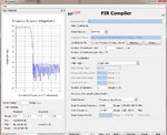
I generated coefficients in matlab for low pass filter and then i use it in xilinx core 5. after I generate the code and pass it to FPGA it doesn`t work!!!!!!!!!!!!!!! input is 16 bit and output must be 16 bit because my DAC is 16 bit. please help me.
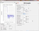
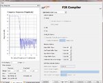
I attached core pictures.
regards
 

Attachments

  • page 1.jpg
    page 1.jpg
    205.9 KB · Views: 57
  • page 2.jpg
    page 2.jpg
    181.5 KB · Views: 62
  • page 3.jpg
    page 3.jpg
    185.2 KB · Views: 59

When you say "it doesn't work" what do you mean? Is your output all zeroes? All ones? No filtering action?
 

it is square wave athe output? is there any problem with my setting? I think it is but I don`t know where? actually I change the output from full preciues to truncat LSB so I can change the output to 16 bit. is this a problem?
thanks
 

I think the truncation is ok. The one thing I would look at is your coefficients. I'm not sure, but it looks like you've got your coefficients as floats in your COE file, but you've declared them as integers in the coregen entry page. You may need to scale your coefficients.
 

well i made them by matlab and before made them I quantize them with matlab in fdatool. coef.jpg
here is coefficient in coregen
 

That looks better (That's not what is shown on your first page of the coregen configuration-they're floating-point coefficients-, but maybe that's ok). Is your square wave output at the same frequency as the input? If so, then you apparently have some gain problem. I would still suspect the coefficients. Have you tried simulation, or are you going right to the FPGA? It might be worthwhile to do a simulation. Try using a lower amplitude input, and see if the output still saturates.
 

yes the output frequency is the same with input ( frequency response of filter is good). I am not using simulation cause I never trust them. I am using my FPGA. I tried all the amplitude from -12db to +12db. it is always like square wave but when the amplitude is very low the pulse width is change and the negative width is smaller than positive one. I also used the coefficients of the FIR core ( those when you open the FIR core is in the coefficient box), the output was still square.
 

First of all, if you don't use simulation, you're going to be wasting a lot of time. Kind of like you are now. It's a lot harder to debug in the hardware than in the simulation.

How do you know you're problem isn't in your ADC? Or something else in your analog chain? Or your power supply? Or your PCB layout?
 

sorry for delay.
My ADC is ok, and all the componnet in my design working well( when there is for filter they work well). I used filter by generating from Matlab, it works well. But untill now I do`nt know what is the problem with FIR core filter but I guess it is amplitude problem( in the frequency domain of FIR core after applying the filter coefficients the maximum amplitude is 80dB!!!!!!!!!!! but in the matlab design we the maxmimum amplitude is 0dB and it will decrease at the end of frequency domain to -80dB. I think the problem is here.
 

That sounds right; as I said, something is wrong with your coefficients. And simulation would have caught this a LOT quicker.
 

that doesn't sound correct. for _integer_ coefficients, you will always have a gain > 0dB for the passband. this is because the normalized coefficients have to be multiplied by a large value in order to give the lower valued coeff's a value that isn't 0. The core should be able to correctly round the outputs to the correct resolution.

I'm suspecting there are some other issues. eg, bus-reversal, incorrect DAC connections (or bit-errors on the MSB), etc... Sim would also pick these up in most cases.

An impulse is a good test signal, as you will get (possibly scaled) the filter's coefficients back on the output.
 

Maybe your problem is on truncation. are you sure about the numbers to be signed/unsigned. i had a similar problem, when i truncated the output (signed), half of the wave appears at top and half at bottom.
 

Status
Not open for further replies.

Similar threads

Part and Inventory Search

Welcome to EDABoard.com

Sponsor

Back
Top