Continue to Site

Welcome to EDAboard.com

Welcome to our site! EDAboard.com is an international Electronics Discussion Forum focused on EDA software, circuits, schematics, books, theory, papers, asic, pld, 8051, DSP, Network, RF, Analog Design, PCB, Service Manuals... and a whole lot more! To participate you need to register. Registration is free. Click here to register now.

[SOLVED] writting pipeline with process

Status
Not open for further replies.

sheikh

Advanced Member level 4
Joined
Sep 10, 2007
Messages
104
Helped
1
Reputation
2
Reaction score
1
Trophy points
1,298
Activity points
2,008
Hello
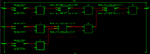
I want to write the following equation with process
F=aX1 + bX2 + cX3 + m
Where a,b,c are coefficients and m is a fix value.
I want to execute it according to the following stages:

S1 : r1=a*x1,r2= b*x2,r3= c*x3
( the above multiplies must execute simultaneously)

S2 : r4=r1+r2, r5=r3+m

S3 : r6=r4+r5

I wrote the above equation in vhdl by using components ( full structural) and it executed pipeline, but I do'nt know how to write it with process. For instance in structural way I wrote S1 by three components and all the multiplies executed pipeline, but how can I do it with process ( do all the multiplies simultaneously! But we know process execute sequentially)

Sorry for a long question and
Hope to see your comments
Thanks
 

You setup pipelined operation by using signals in a process

Code:
process (clk)
  begin
    if rising_edge(clk) then
      -- S1
      r1 <= a*x1;
      r2 <= b*x2;
      r3 <= c*x3;
      -- S2
      r4 <= r1+r2; 
      r5 <= r3+m;
      -- S3
      r6 <= r4+r5;
    end if;  
  end;
 
  • Like
Reactions: sheikh

    sheikh

    Points: 2
    Helpful Answer Positive Rating
Thanks dear Fvm
I did it according to your comment, but what is the following error!

My code:
Code:
library IEEE;
use IEEE.STD_LOGIC_1164.ALL;
entity P1 is
    Port ( X1 : in  STD_LOGIC_VECTOR (7 downto 0);
           X2 : in  STD_LOGIC_VECTOR (7 downto 0);
           X3 : in  STD_LOGIC_VECTOR (7 downto 0);
           O  : out  STD_LOGIC_VECTOR (7 downto 0);
           clk : in  STD_LOGIC);
end P1;

architecture Behavioral of P1 is

signal r1,r2,r3 : std_logic_vector(15 downto 0);
signal r4,r5,r6 : std_logic_vector(7 downto 0);
signal a1 : std_logic_vector(7 downto 0):="00100000";
signal b1 : std_logic_vector(7 downto 0):="00001010";
signal c1 : std_logic_vector(7 downto 0):="00010110";
signal m : std_logic_vector(7 downto 0):="10000000";

begin

process (clk)
begin

if rising_edge (clk) then

-- s1
r1 <= a1*X1;
r2 <= b1*X2;
r3 <= c1*X3;

-- s1
r4 <= r1(7 downto 0)+r2(7 downto 0);
r5 <= r3(7 downto 0)+m;

-- s1
r6 <= r5+r4;

end if;

end process;
O  <= r6;
end Behavioral;


Error:
Line 57: found '0' definitions of operator "*", cannot determine exact overloaded matching definition for "*"

line 57 is "r1"

Regards

- - - Updated - - -

ooopps, I [forgot to add the library
 

you cannot do arithmatic with std_logic_vectors, because they do not represent numbers, just a collection of bits
You need to include the ieee.numeric_std library and use signed/unsigned types.
 
  • Like
Reactions: wtr and sheikh

    sheikh

    Points: 2
    Helpful Answer Positive Rating

    wtr

    Points: 2
    Helpful Answer Positive Rating
Thanks dear TrickyDicky

I wrote the following code based on your comment:
Code:
library ieee;
use ieee.std_logic_1164.all;
use ieee.numeric_std.all;


entity P1 is
   port(X1     : in unsigned(7 downto 0);
        X2     : in unsigned(7 downto 0);
        X3     : in unsigned(7 downto 0);
        clk    : in std_logic;
		  op     : out unsigned(7 downto 0)  
		  );
end P1;

architecture Behavioral of P1 is

signal r1,r2,r3 : unsigned(15 downto 0);
signal r4,r5,r6 : unsigned(7 downto 0);
signal a1 : unsigned(7 downto 0):="00100100";
signal b1 : unsigned(7 downto 0):="00101100";
signal c1 : unsigned(7 downto 0):="00100000";
signal m  : unsigned(7 downto 0):="00100110";

begin

process (clk)
begin

if rising_edge (clk) then

-- s1
r1 <= a1*X1;
r2 <= b1*X2;
r3 <= c1*X3;

-- s1
r4 <= r1(7 downto 0)+r2(7 downto 0);
r5 <= r3(7 downto 0)+m;

-- s1
r6 <= r5+r4;

end if;

end process;
op  <= r6;
end;

The code synthesized but its schematic is strange for me.
2.png
There isn't any multiplier for X3, and this input connected to three flip flop instead of a multiplier ( the blue line in the attached image ).
while the report says that three dsp48 used!
what is the problem?

thanks in advance
 

X3 is multiply by a constant c1 of 32. When multiplying by a power of 2 number, it can be simplified by a left shift.

After that, you are taking only the lower 8 bits of r3 for your sum of r5.

The tool optimized this by taking only the 3 LSB of X3 and padding the remaining bits with '0'. i.e. r5 <= X3(2 downto 0) & "00000" + m;


Just to make sure that I'm right, change c1 to something else like 31 and check for the synthesis result.
 
  • Like
Reactions: sheikh

    sheikh

    Points: 2
    Helpful Answer Positive Rating
You get exactly the logic that is described by your VHDL program.

I guess, you didn't yet consider what the program means. E.g. c1 in combination with stripping the 8 most significant result bits of the multiiply results in only 3 bits from input x3 being propagated and 5 bits ignored.

I suggest to visualize your logic description with pencil and paper method, or using a pocket calculator.
 
  • Like
Reactions: sheikh

    sheikh

    Points: 2
    Helpful Answer Positive Rating
Thanks dear Tetik, you were right :)

3.png

Thanks dear Fvm for your advis :)
 

Attachments

  • 3.png
    3.png
    23.8 KB · Views: 82

Status
Not open for further replies.

Part and Inventory Search

Welcome to EDABoard.com

Sponsor

Back
Top