Continue to Site

Welcome to EDAboard.com

Welcome to our site! EDAboard.com is an international Electronics Discussion Forum focused on EDA software, circuits, schematics, books, theory, papers, asic, pld, 8051, DSP, Network, RF, Analog Design, PCB, Service Manuals... and a whole lot more! To participate you need to register. Registration is free. Click here to register now.

Would this allow motor control in both directions?

Status
Not open for further replies.

Resistanceisfutile

Member level 4
Joined
Aug 22, 2012
Messages
77
Helped
2
Reputation
4
Reaction score
1
Trophy points
1,288
Activity points
2,008
So I was wondering whether this circuit (apologies for the awful paint drawing) would allow me to control a motor in two directions?
(If there are any other nessecary components please tell me.)
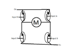
Dual motor config.png
Just for clarification, I'm asking whether when input A or B was high (and the other input was low) would the motor turn properly?
 

The H-bridge configuration is O.K., an appropriate base/gate drive circuit is missing yet. I believe you'll find dozens of similar threads at Edaboard.

Just for clarification, I'm asking whether when input A or B was high (and the other input was low) would the motor turn properly?

If "A or B was high" means actual voltage levels, the answer is possibly no. You should elaborate the circuit by putting in recognisable switch components and ask again.
 

the attached circuit will not work.
needs lot of modification.
 

If those are transistors and the motor is a DC reversible type, yes it will work.

What you have to take into account is the 'A' signals and 'B' signals must never overlap or you create a short circuit across the supply. Also note that you can't directly link the two 'A' or two 'B' signals because the voltage to drive the transistors is on the base relative to the emitter pins and the 'top' one in the bridge will have it's emitter at motor voltage while the bottom one will be at ground voltage.

Brian.
 

I do not know what your awful semiconductors are. I also use Paint and I copy and paste proper images of parts from other circuits or datasheets.
You need an H-Bridge Circuit. Look in Google Images for hundreds of them but many do not work properly.
 

Hi,

These links are a good place to copy reliable H-Bridge circuits:

**broken link removed**

**broken link removed**

I learnt how to make one (that worked) using the first link, and it provides two different configurations to work from.


"Look in Google Images for hundreds of them but many do not work properly. " - too right, there are even sections of web pages dedicated to explaining which pointless H-Bridge schematics around the 'net are a waste of time and very frustrating to copy ("...nothing's happening/those transistors are unusually hot/why is the motor not quite starting to turn?/ why is it only spinning in one direction?..." :)).

How will you drive the bridge's inputs for your bi-directional motor? You can do it mechanically with a double pole switch ("on-off-on" type I think it's sometimes called) to reverse the direction (or if it is a momentary use with two pushbuttons), or some type of IC, or maybe you use an Arduino or similar.

You can place a buffer IC between the inputs and the rest of the circuit. You may need to place diodes between the transistors and the motor (from the motor terminals to V+ and to V-/0V) due to the back-emf it will put out when turning off.

If you're interested in a quick and easier way to draw your ideas/circuits, there are loads of "Schematic capture" software programs: DesignSpark is one, and it's extremely easy to use, Spice based ones are many, and the list is endless.

Good luck with that!
 
Last edited:

Status
Not open for further replies.

Similar threads

Part and Inventory Search

Welcome to EDABoard.com

Sponsor

Back
Top