lifiq
Junior Member level 2
#define intruder PORTB.f7
#define button_ON PORTB.f6
#define blockcar PORTD.f7
char j[10] = "AT+CMSS=1"; // COMMAND SEND MESSAGE FROM
int enter = 0X0D; // COMMAND FOR ENTER
char i;
void main()
{
trisb = 0xff; // SET PORTB AS INPUT
portd = 0x00; // SET INITIAL VALUE FOR PORTD
trisd = 0x00; // SET PORTD AS OUTPUT
uart1_init(9600); // SYNCHRONIZE BAUDRATE WITH HANDPHONE
trisc.f7 = 1; // SET Rx DATA IN
trisc.f6 = 0; // SET Tx DATA OUT
while(1)
{
ON:
while(1)
{blockcar=0;
if(button_ON==0)
{
goto ON;
}
else if (button_ON==1)
{
goto INTRUDER;
}
}
INTRUDER:
while(1)
{ if((button_ON==1)&&(intruder==1))
{
goto SSMS;
}
}
SSMS:
while(1)
{ for(i=0;i<10;i++)
uart1_write(j); // SENDING CHARACTER FOR SENDS SMS
uart1_write(enter);
goto USERINT; // GO TO BLOCKING CAR
}
USERINT:
while (1)
{ blockcar=1; // BLOCKING THE CAR
if (button_ON==0) // WAIT FOR USER INTERRUPT
{goto ON; // BACK TO START AFTER USER INTERRUPT
}
}
}
}
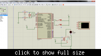
this is my code that i wrote on my pic18f452...it works fine on proteus....i have 2 input pins which are pin 39 for start and pin 40 for intruder detection.....but when i implement it on breadboard.....when i put 5v input on the start pin 39....it triggers the output pin 30....but the output is not 5v voltage level but lesser than that....why is this happening....i used pic micro pro 4.15 to compile the code and when i import it onto proteus it works fine....what am i doing wrong?
