Continue to Site

Welcome to EDAboard.com

Welcome to our site! EDAboard.com is an international Electronics Discussion Forum focused on EDA software, circuits, schematics, books, theory, papers, asic, pld, 8051, DSP, Network, RF, Analog Design, PCB, Service Manuals... and a whole lot more! To participate you need to register. Registration is free. Click here to register now.

working of a simple circuit

Status
Not open for further replies.

geo_18

Newbie level 5
Joined
Sep 22, 2013
Messages
8
Helped
0
Reputation
0
Reaction score
0
Trophy points
1
Activity points
59
Dear friends,
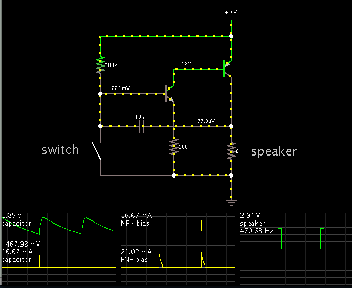
Please help me to understand the working of the simple circuit i have attached here.

portable-alarm-for-personal-use-1327170038.gif


Here Q1 - BC547 and Q2 - BC 327.
R1 = 300k ohm, R2 = 100 ohm, C2 = 100 uF, C1 = 10nF. The battery used is 3Volts.

This is the circuit of a personal alarm. When the switch turns open, the speaker sounds aloud.
I would like to know how the speaker sounds when the switch turns open and how the capacitors aid in the working of this circuit. Also, is there any difference between the working of the pnp and npn transistors??

Please do help me soon.
 
Last edited:

its quite simple.as q1 is npn transistor it need is positive supply to make the circuit work while switch is in close the negative power is supplied hence it wont work i mean alarm in off. once switch opens..positive power is applied to switch through resistor .hence circuit works..if u have any doubts dont hesitate to reply
 
  • Like
Reactions: geo_18

    geo_18

    Points: 2
    Helpful Answer Positive Rating
Thank You so much for the reply, was of a great help. Could you also please tell me the probable use of the capacitors in this circuit?? And also how are the two transistors working together in this circuit..??
 

Both transistors together make an amplifier that has the output at the same phase as the input. C1 couples the output signal to the input, the transistors amplify the signal and the signal goes around and around as an oscillation.
 
Both transistors together make an amplifier that has the output at the same phase as the input. C1 couples the output signal to the input, the transistors amplify the signal and the signal goes around and around as an oscillation.

why do we want to amplify.the circuit works on open swith .so bas voltage is set by Rb resistance.if i use some sensor and i gave that output to input of base..i agree your point of amplification..but why its here used,we can also make it with single transistor.right
 

1) The capacitor charges slowly,
2) until the left-hand node is at a high enough volt level to turn on the NPN transistor.
3) When the NPN turns on, it pulls the PNP bias low, turning it on.
4) The PNP conducts a burst of current, which goes through the speaker.
5) The capacitor receives a current burst, charging it in the other direction.
6) The process repeats.

To grasp the operation of an oscillator, it is especially helpful to watch it in animation. To see current flowing in the wires. Not to mention scope traces on several components.

This is a screenshot of the schematic as I laid it out in Falstad's interactive animated simulator.


To see what I see, and see it running on your computer...

Click the link below. It will open the website falstad.com/circuit, and load my schematic above.

https://tinyurl.com/m8756cs

Notice the colors which indicate volt amplitude and polarity.
The left-hand node goes as low as -1.8 V for a time (even though the supply V is positive).
 
  • Like
Reactions: geo_18

    geo_18

    Points: 2
    Helpful Answer Positive Rating
Status
Not open for further replies.

Similar threads

Part and Inventory Search

Welcome to EDABoard.com

Sponsor

Back
Top