Continue to Site

Welcome to EDAboard.com

Welcome to our site! EDAboard.com is an international Electronics Discussion Forum focused on EDA software, circuits, schematics, books, theory, papers, asic, pld, 8051, DSP, Network, RF, Analog Design, PCB, Service Manuals... and a whole lot more! To participate you need to register. Registration is free. Click here to register now.

Working of a FM receiver

Status
Not open for further replies.

garvind25

Full Member level 3
Joined
Oct 28, 2012
Messages
176
Helped
0
Reputation
0
Reaction score
1
Trophy points
1,298
Activity points
3,066
Hi,

I came across this schematic for a FM receiver on the internet (**broken link removed**). I was trying to understand its working.
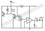
small-fm-radio.jpg

It is clear that the LC coil will tune to the FM carrier + message signal of the FM station. LM 386 will amplify the message signal demodulated from the tuned signal and drive a speaker /headphone. But I am unable to understand the working of T1, T2, R1, C2 and VR. Most probably, some of these components are demodulating the tuned FM carrier + message signal. But I am not clear of the functioning. Could anyone tell me how the demodulator is working? Which type of FM demodulator is it?

Looking foward to your replies.

Thanks and Regards,
Arvind Gupta.
 

It isn't an FM receiver, it is a super-regenerative AM receiver but it will receive FM using slope demodulation. Basically you don't tune to the station, you tune 'beside' it and the recovered audio comes from the carrier moving closer or further away from your tuning point. Expect poor results!

VR is the volume control, C3 is there to make the LM386 less stable and to increase distortion! This kind of receiver is sensitive but has poor bandwidth, poor audio quality and has a tendency to interfere with other nearby frequencies. The tuning will be tricky because your proximity to the antenna shifts the frequency.

Brian.
 
C3 is there to make the LM386 less stable and to increase distortion!
In other words, you better replace it by the Boucherot cell given in the LM386 datasheet.
 
Thanks for the explanation. Can you suggest a better FM receiver - simple yet robust?

Regards,
Arvind.

- - - Updated - - -

In other words, you better replace it by the Boucherot cell given in the LM386 datasheet.

OK. Any ideas how to find the value of L of a speaker/set of earphones which will be driven by the LM386? Is there any standard value assumed during calculations? The datasheet of LM386 here mentions a capacitor of 0.05 uF in series with a resistor of 10 ohms ! (usually small speakers, as I have seen, have resistances of 8/16 ohms).
 

Simple and FM don't go together in the same sentence but if you search for 'pulse counting discriminator' it should throw up some ideas that don't need special inductors or PLL ICs.

The LM386 will drive almost any loudspeaker or headphones but like almost all other amplifiers it should not have a capacitive load connected across its output. If you add a 10 Ohm resistor in series with a 100nF capacitor it will work far better.

Brian.
 
mentions a capacitor of 0.05 uF in series with a resistor of 10 ohms

RC time constant is very short. I'm pretty sure the purpose is to inhibit high frequency howling.

Notice the headphone icon is in series with hundreds of uF (to block DC but admit AC). It's the usual strategy with single-polarity supplies. Over 1000 uF is recommended to carry higher watts, or deep bass frequencies.
 

I agree that the extremely simple FM regen circuit is garbage. Usually a simple circuit produces poor performance.
Most real FM radios have at least 5 lC tuned circuits for gpood selectivity. This circuit has only one tuned LC circuit so it might pickup 5 stations at the same time. Its sensitivity is very poor. Since it has an AM detector then it will produce all the static noises heard on an AM radio and its sound will be very shrill because it is missing the de-emphasis filter that all real FM radios have.

An application note for the older and similar LM380 audio amplifier IC explains that the Boucherot cell or Zobel network suppresses a 5MHz to 10MHz oscillation caused when the inductance of a speaker causes the load impedance to be high. The oscillation causes audio distortion. The amplifier might oscillate with the missing resistor of the Boucherot cell.
 

Status
Not open for further replies.

Part and Inventory Search

Welcome to EDABoard.com

Sponsor

Back
Top