Continue to Site

Welcome to EDAboard.com

Welcome to our site! EDAboard.com is an international Electronics Discussion Forum focused on EDA software, circuits, schematics, books, theory, papers, asic, pld, 8051, DSP, Network, RF, Analog Design, PCB, Service Manuals... and a whole lot more! To participate you need to register. Registration is free. Click here to register now.

Working at 1500V

Status
Not open for further replies.

roiberts

Junior Member level 1
Joined
Nov 11, 2019
Messages
19
Helped
0
Reputation
0
Reaction score
0
Trophy points
1
Activity points
194
Dear Forum

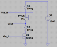
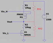
i have a voltage divider ,supplyed with 800V, formed by 2 resistor R1 R2 of 1Mohm each one (in realty
i connect more in serie for divide the power) ,so the current is some mA . Because I need to open and
close current flow,as switch I use a N-MOS in the lower side of partition (with Source to GND and Drain to R2 ) ,
or, in alternative, a PMOS or OptoMos ,in upper side of partition (with Source to Power and Drain to R1).

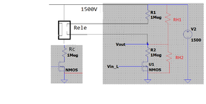
Now I need to work at 1500V,and here I have some problem in find the right MOS.

At this voltage, i find a NMOS (VCEO up to 1700V) but not a PMOS(VCEO max 800V) . So, no problem for interrupt the
low side of partition, but yes to interrupt the upper side.

So, first question is:

1)Why PMOS dont stand a VCEO as NMOS ? Also, non PNP for 1500V . No chance to interrupt the upper side of partition.

2)Another intresting fact is that all MOS i find are rated for hight current ( many ampere), while, in my circuit flow some mA,
Ths make MOS more expensive and bigger . No HV mos and low current ?

3)No optocoupler o opto mos to this voltage ,but I find IGBT support 1700V(10A !!!),and they have PNP supporting such VCE.

Is the IGBT the only solution for Hight side switch

Thanks for your help and time spend for me

Roberto
 

Solution
I won't expect higher switching rate or even frequent switching with an isolation tester. standexmeder HE series with up to 10 kV switching voltage should do, probably also smaller reed relays.
--- Updated ---

Typical lifetime specification of reed relays is 10^5 - 10^6 operations at rated load and 10^9 unloaded.
Hi,

rather unclear.

You say 800V.
--> DC? or AC? Which frequency range?

You say "some mA", but 800V / (2 x 1MOhm) gives 0.4mA

--> what is the output of the voltage divider used for?

--> Why do you need to open/close the current flow?

--> Now you say you need to work with 1500V ... before it was 800V. Please calrify

--> Why MOS, why not BJT?

to your questions:
1) I guess they don´t build them, because there is not much demand for them.

2) I guess because high voltage means high isolation distance on the silicon chip, that also means high silicon area = expensive. So it´s not much more expensive to design them for higher current. And again, I think there is not much demand for low current, high voltage.

3) IGBTs usually are for high power (btw: you are posting in the POWER section..) means high voltage * high current.


--> A (hand drawn) sketch and some more information will help us to help you.

Klaus
 

Thanks for Reply Mr Klaus

in Attach is the circuit we want create, for 1500V DC voltage.
The NMOS I find ( SCT2H12NY) support VCEO 1700V,.and it is OK.
The PMOS side I cant find ......Also searching for PNP give not result.

Only solution is via IGBT (IXGT10N170 ) ,stans also 1700V

I would like also to isolate from the Gate Driver,so , I would like to find a opto isolator,
but, seems impossible over 1500V.

Any suggestion is welcome.

Thanks
Roberto
 

Attachments

  • NPMOS.PNG
    NPMOS.PNG
    11.6 KB · Views: 85

@roiberts What are you trying to achieve?

Your attached Spice schematic makes no sense to me, because you are already forming a voltage divider by the resistors why the additional mosfets? If you just switched on the upper PMOS then current would flow through the 1Mohm resistor to load , if you switched on both mosfets then you would have a resistor voltage divider, so what's the use of mosfets at all in this schematic I see no use for them, because if you want for the schematic to work as a voltage divider then you can just connected the resistor with wires instead of mosfets but if you want to control the load (switch on off) then you need just one mosfet not two.
Also notice that if you use the schematic as voltage divider then you don't need mosfets with voltage rating of 1500V , putting the mosfets between the two resistors there is only half the voltage , so you could do with 800v or for sdatefy say 1000v

Anyway please tell us what are you trying to do here so that we can make more sense
 

Thanks for reply

NO secret..excuse..I belive was not so important for the reply.

Owr client working in medical instruments, want a test circuit for measure isolation beetwen the 2 PCB part of this
product,with the scope to be sure the final user dont remain injured.
Measure consist in finding the value of 2 resistor, from 1500 to Vout, and from Vout to GND.
The 1500 is on one side of PCB, Vout on the other.
So, 2 measure, 2 equation.

Mr Salvador, thanks for reply : but, when you opern one mos, and the other is clodes, all voltages goes on the
open MOS.

Thanks for your reply

Roberto
 

Hi,

for me it sounds contradicting.

* in post#1 you talk about a voltage divider. Now it sounds as if you never want to divde voltage.
* in post#1 you talk about a "low side switch" or alternatively "a high side switch", now it sounds as if you wont both.

I´m really confused. Don´t know what you really need.

Good luck

Klaus
 

For find 2 resitor, that means, 2 incognit, you need a partition.and create 2 equation, as i mentioned last message.

If we need to go in detail, i can give more info how to measure isolation, but this means write some equation.,and
a question about MOS became a math post.
But I can do..no problem.

Anywai, I cant understand why it is so important: can not this circuit be a game ,just for try it, or must have a real
function for get a reply?

This means, I cant get reply because nobody is using ?

Thanks

Roberto
 

Hi,

its also possible to use multiple PMOSs in series with a lower rated Drain to Source voltage. But than you have to ensure they are closing at the same time, which is hard to accomplish, one migth close faster than the other one (assuming two PMOSs in series). Consequently the one getting non-conductive earlier might be epxosed to the full 1500 V. You can overcome this issue by placing zener diodes in parallel to the PMOSs limiting the voltage across them. The current through your zener diodes is limited by your 2 • 1 Meg resistors.

BR
 

Thanks FVM and Stenzer.

I will try and will update about owr final result.

Thanks

Roberto
 

It appears the OP wants a switch to measure 1500V - by stepping it down to half of this - i.e. 750VDC

it is unfortunate the OP did not state this at the outset - along with how often this measurement needs to be made - which affects how one would go about it.

Using 1700V mosfets - there will still be a leakage current at 0v gate-source - which will affect measurement - so the OP needs to also advise what accuracy is desired also.

Thus for very low frequency of measurement some sort of relay may work well, but for higher frequencies of measurement relays will not last over years of use.
 

I won't expect higher switching rate or even frequent switching with an isolation tester. standexmeder HE series with up to 10 kV switching voltage should do, probably also smaller reed relays.
--- Updated ---

Typical lifetime specification of reed relays is 10^5 - 10^6 operations at rated load and 10^9 unloaded.
 
Last edited:

Solution
Hi,

Using 1700V mosfets - there will still be a leakage current at 0v gate-source - which will affect measurement - so the OP needs to also advise what accuracy is desired also.

I agree, the leakage current has to be considered. But I'm not worried about the measurement itself, therefore I assume both MOSFETs are turned on. Consequently, the leakage current has no effect (isn't present). Further, the maximum zero-gate current of the previous mentioned NMOS [1] is 10 µA (@ 25°C). This corresponds to 1.33 % compared to the on-current of 750 mA (1500 V / 2 Meg), or 10 V @ 1 Meg.

I would be more concerned about the overal system, as the zero gate leakage current may lead to a bould up of a hazardous voltage i.e. if the measurement system is galvanically isolated and the housing is made of metal (high ohmic leakage path from HV towerds LV side).

BR
 
Thanks Stenzer, Fvm and Easy for reply.

As Stenzer saym the zero current is max 10uA, that correspond to

1500/10uA= 150Mohm

when mos is open, and, this is trascurable when parallel with a R isolation to measure..

I will be more clear about how we will do the measure (in case this helps).
In attach you have the same schematic of last time (FIG 1), but in red i higlighted the 2 resistor we need to measure; this 2 resistor are the isolation resistor due to air, case ecc.

This resistor seems to be tipical around some Mohm.

We have 2 incognit, RG1, RG2, so we need 2 equation for solve them.
1 Equation comes from opening M1, closing M2, and measure the Vout
2 Equation comes from opening M2 ,closing M1 ,and measure the Vout (that will be different)

So, solving the equation , we have RH1 and RH2

As I sayd, the NMOS i find for 1700V, but the PMOS not.

Relay seems the solution ,or In alternative I find a IGBT .

Now, Im thinking, that Rele or IGBT ,both need a tipical -open collector- driver circuit (FIG 2 , to put Rele or IGBT on /off), that is ,another NPN (o NMOS) with a Rc on collector,(or Drain) ,and then Rele (IGBT) and then to 1500V.
This Rc (from 1500V generator to gnd) ,disturb my equation because Rc could compete with RH1 RH2

Working at 1000V or less, we have no this problem; The PMOS or IGBT was substitute by a PhotoMos, so,
driving him with some mA to 3.3V, we put On/Off the Photomos ..NO driver circuit needed connected to 1000V..No distrurb of the measure.

Now,at 1500V, no Photomos.

Thanks for support and excuse for long mail

Roberto
 

Attachments

  • FIG1.PNG
    FIG1.PNG
    14.4 KB · Views: 86
  • FIG2.png
    FIG2.png
    18.5 KB · Views: 85

If we assume 1x, or 2x 1700V Si mosfet - such as STFW3N170

which is 10uA @ 25degC ( 500uA @ 125 degC ) - properly driven

then the problem is solved, a simple 100kHz ( or higher ) rectified isolated Tx ( signal ) could be used to drive the high side ( and low side for safety ) assuming the sensing frequency is fairly low ( < 1kHz )

For a common ground system a single high side device is all that is needed, this could operate a divider chain to give 15V for 1500V.
 

small 100kHz or higher isolating Tx wound on a toroid ( or EE15 say ) ( teflon coated each wire for isolation ) - run 100kHz 12V square wave into it for ON

on other side rectify ( 4 x 1n4448's ) and apply to gate, along with a bleed R for turn off, and an extra 1n0 to hold the volts in the short dead time from the Tx.

stop the drive for off.
 
Thanks very much to everyone reply to my question.

We will work under 1500V, and so using optomos that can stand 1500V. it seems the fast way to do it

Thanks again

Roberto
 

I often design flyback converter with high input voltage.
Using Nmos in Cascode configuration is suitable for your application.
 

Status
Not open for further replies.

Similar threads

Part and Inventory Search

Welcome to EDABoard.com

Sponsor

Back
Top