Continue to Site

Welcome to EDAboard.com

Welcome to our site! EDAboard.com is an international Electronics Discussion Forum focused on EDA software, circuits, schematics, books, theory, papers, asic, pld, 8051, DSP, Network, RF, Analog Design, PCB, Service Manuals... and a whole lot more! To participate you need to register. Registration is free. Click here to register now.

Wireless transmit / receiver

Status
Not open for further replies.

jmorrone

Newbie level 2
Joined
Jul 28, 2011
Messages
2
Helped
0
Reputation
0
Reaction score
0
Trophy points
1,281
Activity points
1,295
I just received this transmitter receiver kit and I am trying to get it to work but I am not sure I have things set right. I am attaching a diagram of what I have done. If anyone can help me with this I would greatly appreciate it. Thank you.

oh and here is a link to the pdf that they gave me on setup.

https://www.robotshop.com/ca/content/PDF/how-to-use-315mhz-remote-relay-kits-wls103b5b.pdf

~James
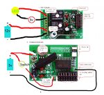
circuit.jpg
 
Last edited:

Have you check this.................

(2) Choose the pins corresponding with remote relays you want to control.
1- Useless for 2 channels remote relay switch
2- Correspond with relay labled 2 on figure 1.
3- Useless for 2 channels remote relay switch
4- Correspond with relay labled 4 on figure 1.
First remove all the shunts, and then connect the pin 2 or/and pin 4 to +5v.
 

By that don't they just mean remove all jumpers, then replace the jumper for the relay you want to use? Or do i actually have to wire something directly to the jumper. Currently the only jumper on is the one for relay (2)

Have you check this.................

(2) Choose the pins corresponding with remote relays you want to control.
1- Useless for 2 channels remote relay switch
2- Correspond with relay labled 2 on figure 1.
3- Useless for 2 channels remote relay switch
4- Correspond with relay labled 4 on figure 1.
First remove all the shunts, and then connect the pin 2 or/and pin 4 to +5v.
 

I dont have schematic of this card, only read what is written in guide sheet.

You should check is selected jumper pin connected to +5V ( volt meter to pin and gnd)
if there is 0V , when jumper is placed,
then remove jumper and try connect +5V to pin via 1kohm resistor.
( or ask help from shop you bought this card )
 

Status
Not open for further replies.

Part and Inventory Search

Welcome to EDABoard.com

Sponsor

Back
Top