Vermes
Advanced Member level 4
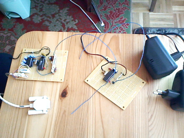
This system allows the wireless temperature measurement using DS18B20+. Temperature is displayed in the console of Windows system.
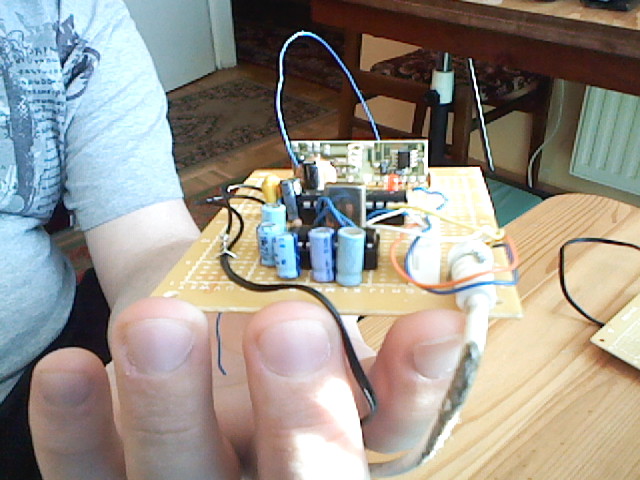
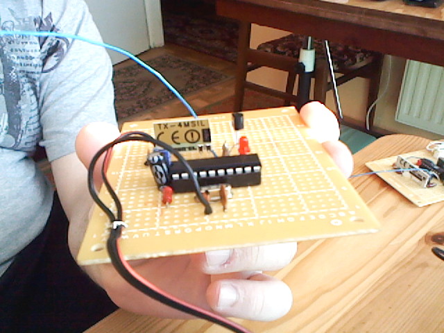
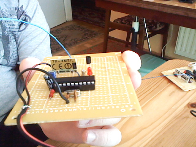
Transmitting:
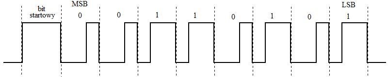
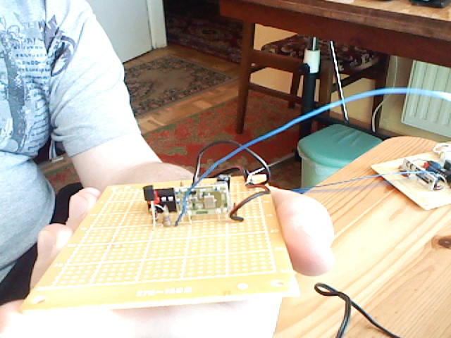
It consists of a microcontroller AT89C2051, transmitter module TX-4MSIL from Aurel and DS18B20+. 1Wire interface was implemented in software. The microcontroller reads the temperature bytes from the memory DS18B20+. Then it adds a phasing byte (the beginning of the frame). So prepared three bytes are subjected to channel coding. In the presented device, channel coding is amplitude-time (as in the DCF system). Logic “0” is presented as a pulse with a duration of 1/3 of bit gap. Logic “1”is 2/3 of bit gap. Each of the sent bytes bears the start bit, which is a pulse with a duration of the entire bit gap. The signal after passing through the channel coding process then goes to data line of the transmit module.
Example byte:
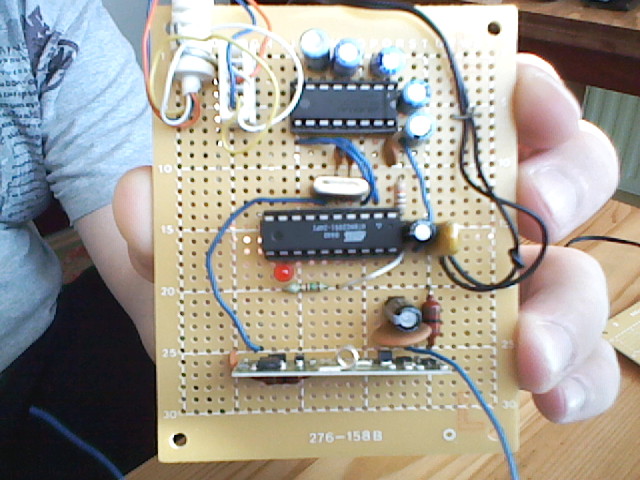
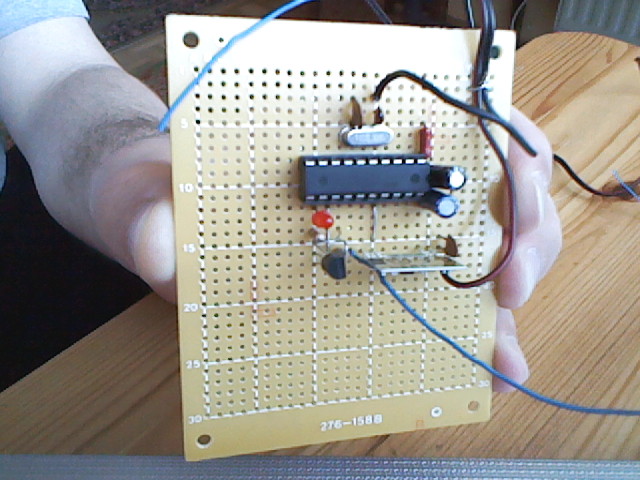
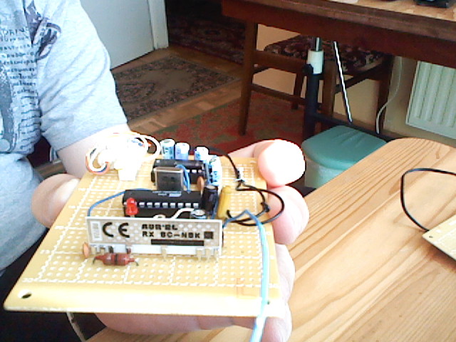
Receiving:
In this block, as in the transmitting, microcontroller AT89C2051 was used. Also receiving module RX-BC-NBK from Aurel and voltage level converter MAX232 are parts of this module. The microcontroller waits for the start bit. After receiving the start bit, data bits are sequentially received. The received byte is sent to a PC via RS-232 interface. The application written in C++ waits for byte phasing the frame. After receiving it, two temperature bytes are received. Then the correctness of received frame is checked. The system does not use CRC-N method, it uses only a simple control of the range of temperatures, the values of received bytes, the control of the extended bit sign, etc. If the transmission proved to be correct, the application calculates the fixed point U2 to the number suitable for display in the console system.
Despite the simplicity of the device, it works very well. Also, control of transmission errors is sufficient. Wireless transmission protocol used also proved in practice. It turned out to be a far better solution than the use of hardware UART microcontroller. Unusual quartz resonator 3,579545MHz (as for 8051, it is a typical “TV” quartz from NTSC) in the receiver is an effort to raise the standard speed of asynchronous transmission for RS232. With the resonator used, the bandwidth is slightly less than 57600b/s. However, it falls on the permissible error, which is 4%. The software for the microcontroller was written in assembler.
Link to original thread (useful attachment) – Bezprzewodowy pomiar temperatury.