Continue to Site

Welcome to EDAboard.com

Welcome to our site! EDAboard.com is an international Electronics Discussion Forum focused on EDA software, circuits, schematics, books, theory, papers, asic, pld, 8051, DSP, Network, RF, Analog Design, PCB, Service Manuals... and a whole lot more! To participate you need to register. Registration is free. Click here to register now.

wireless energy meter

Status
Not open for further replies.

Kick

Full Member level 6
Joined
Sep 27, 2010
Messages
344
Helped
16
Reputation
32
Reaction score
15
Trophy points
1,298
Location
India,Bangalore
Activity points
3,170
Hii friends,

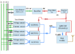
Have anyone working on wireless energy meter (Wifi or BLE)? let say smart energy meter. dsPIC33 may be the microcontroller. Now I have completed block diagram, I need some suggestion/advice from you guys.

Thanks
 

Wireless E or H field depends on gap loss and coupling for current, frequency and Loaded Q of detector among other things.

it is best to use a good receiver and monitor RSSI signal.
 

Thanks for reply. This is my block diagram of circuit(3-phase). Is it right way to measure power?
 

Attachments

  • block dig.png
    block dig.png
    39.7 KB · Views: 70

There are many ways to multiplex inputs, ANalog or in your case digital with a single ADC per phase multiplexing SPI. The optimal, depends on accuracy specs, cost and reliability. Details in specs not shown can alter any outcome.

So start with a product design spec for everything.
 

Thanks SunnySkyguy

Actually I want better isolation (galvanic isolation) of DC part from high voltage AC part. I knows that Transformers and Opto isolators are better option for isolation. The thing is Transformers need lot of space in PCB(3 transformers for 3-phase) and also cost, so I am just thinking to use opto isolator to reduce PCB size. Can you guys suggest some opto isolator for 230V ac ? Project is power measurement of AC supply.
 

Nearly all electronic energy meters are connecting the analog front end galvanically to the power lines (usually circuit ground to neutral) and using voltage dividers to measure the line voltage.

Adding isolation transformers to th evoltage measuremet already affects the energy meter accuracy and any cheap opto coupler would dwart it completely.

In a wireless energy meter, you won't need any isolation means, except during development and test.
 

With "second point" you mean transformer and optocoupler errors?

A transformer generates phase errors and nonlinear distortions.

An analog opto isolator suitable for energy meter input signals usually implements internal ADC/DAC conversion and digital isolation. Simple linearized analog couplers have typically several percent gain and linearity error.
 
  • Like
Reactions: Kick

    Kick

    Points: 2
    Helpful Answer Positive Rating
This would be my circuit: AC main---> optocoupler(SFH series)---> AFE(MCP3911)-----SPI------> uC(dsPIC33F)---> RF circuit.
 

I'm not aware of a particular SFH optocoupler suitable for analog signals. Which do you consider?

Actually I want better isolation (galvanic isolation) of DC part from high voltage AC part.
I didn't yet hear a motivation for this statement. As said, analog isolation is unusual for 230/400V energy meters.
 

So are you saying in my circuit isolation(optocoupler) is not required? I think there should be protection part from shock .....confused :???::thinker:
 

Status
Not open for further replies.

Part and Inventory Search

Welcome to EDABoard.com

Sponsor

Back
Top