Continue to Site

Welcome to EDAboard.com

Welcome to our site! EDAboard.com is an international Electronics Discussion Forum focused on EDA software, circuits, schematics, books, theory, papers, asic, pld, 8051, DSP, Network, RF, Analog Design, PCB, Service Manuals... and a whole lot more! To participate you need to register. Registration is free. Click here to register now.

Wire ultrasonic sensors to solenoid valves

Status
Not open for further replies.

tmc6891

Newbie
Joined
Feb 19, 2023
Messages
5
Helped
0
Reputation
0
Reaction score
0
Trophy points
1
Activity points
48
Evening all. I am new to this and am rubbish at electronics. Hopefully I can get some good advice here.
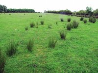
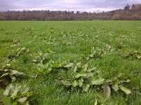
I was going to modify a atv sprayer boom so that I could fit some ultrasonic sensors beside each nozzle and wire it to a solenoid valve which will be plumbed to the pipework of the sprayer. The particular weed I am spraying sticks up out of the ground anything from 200mm to 600mm. I was hoping the ultrasonic sensors would detect this particular weed and activate the corresponding nozzle via solenoid valve. Therefore not having all the nozzles running constantly, only when needed and not wasting chemical. Hope this makes sense. In theory it should work. Where I am from, we can use an implement called a weed wiper but I was thinking this idea would apply a good accurate dose of chemical to the target weed.
But I would have no clue where to start when it comes to the electronics side of things,
How is it wired,
Do I need replys,
Would I have enough power from atv(12volt) to power pump, solenoids and sensors? Etc etc.

Any advice would be greatly appreciated.
 

I suppose you plan to broadcast ultrasonic noise first? So you can detect echoes from plants which are at 20-60 cm height? Causing a solenoid to turn on the sprayer?

(Or you might choose a high-tech radar type of detector which works on ultrasound (or else radio waves), as might be used on automobiles to avert collisions.)

Or it may work better to detect plants optically. Say you mount a camera at knee height, and if it detects a plant directly in your path, the sprayer activates? A camera aimed at the sky would detect a plant as slight dimming of the light.
Thanks for your reply Brad,
Isn't that the idea of a ultrasonic sensor?

Going high-tech sounds expensive.
Is the camera option expensive? Could possibly play about with different options but I just need a general starting point and how to go about it.
 

It's hard to picture spindly plant stems reflecting acoustic echoes. Instead we hear of ultrasonic ranging done with solid objects, walls, etc.

Does the weed have a distinctive color? It might work to have a single photo-sensor exposed to light coming through a filter matching the color of the weed.
Or, a particular wavelength of light unique to the weed, or its bloom, or seedpod.
The wavelength might be infra-red or ultraviolet, detectable when illuminated with a certain type of lamp.

Another option is dash cams and backup cams for cars. Some are inexpensive. The digitized image could be examined by a computer program which looks for pixels in a certain range of color values.
 

I think the problem here is how to distinguish unwanted weeds from plants you want to protect. Other than height, is there anything else that makes it easy to identify which it is?

Ultrasonics can be used but they work by measuring reflected sound and in the case of a plant where there are unlikely to be hard and parallel surfaces for the sound to bounce back from, the received signal might be weak and poorly defined.

If height is the only distinguishing feature, a simple spring wire opening a nozzle would be by far the cheapest and simplest option.

Brian.
 

Thanks guys, this is great. Very informative. I just assumed that ultrasonic sensors would bounce off any object. See attached the 1st image of the weed rush. This is the main weed I would be aiming to tackle. As you can see it's very straight, pointy and stemy and sits up well past the grass that would be hoping to protect. Notice how it's dotted around the field in small clumps, hence why I would like to try and make something that comes on when required.
The 2nd image is of the weed docks that we sometimes have to control but not as much as rush. This is a lot more low lying and has a very distinct broad green leaf. Perhaps a photo sensor would work here?
You may ve able to make a better judgement of the attached photos.

Thanks again.
 

Attachments

  • 15251-151563.jpg
    15251-151563.jpg
    65.2 KB · Views: 84
  • 39796_1.jpg
    39796_1.jpg
    82.6 KB · Views: 88

A single photo-sensor at ankle height would get dimmed as it nears a clump of the dark green weeds. Aim it at an angle to produce maximum contrast whenever a weed clump blocks the sky.

The electronics could consist of an op amp, powering a transistor, which in turn powers a relay, which in turn powers a solenoid. (I guess your word 'replys' refers to relays in post #1?)

Various inexpensive photosensors are an option. Cadmium sulfide cell, solar cell, phototransistor, photodiode, Infra-Red receiver (this last component resembles an led).

The circuit (first stage of amplification, that is) is a simple project we'd find in a grade-school '100-in-1 projects' electronics trainer. Simply adjust the trigger point between bright/dark level.

The remainder: transistor, relay, solenoid are needed to step up the power to operate a nozzle. It requires familiarity working with such components.
--- Updated ---

The second picture shows broad leaves which are bright and glossy. They look like they shine in sunlight.

For these, a photosensor at knee height, aimed downward. Adjust op amp threshold so it turns on when exposed to brighter light.
 
Last edited:

A single photo-sensor at ankle height would get dimmed as it nears a clump of the dark green weeds. Aim it at an angle to produce maximum contrast whenever a weed clump blocks the sky.

The electronics could consist of an op amp, powering a transistor, which in turn powers a relay, which in turn powers a solenoid. (I guess your word 'replys' refers to relays in post #1?)

Various inexpensive photosensors are an option. Cadmium sulfide cell, solar cell, phototransistor, photodiode, Infra-Red receiver (this last component resembles an led).

The circuit (first stage of amplification, that is) is a simple project we'd find in a grade-school '100-in-1 projects' electronics trainer. Simply adjust the trigger point between bright/dark level.

The remainder: transistor, relay, solenoid are needed to step up the power to operate a nozzle. It requires familiarity working with such components.
--- Updated ---

The second picture shows broad leaves which are bright and glossy. They look like they shine in sunlight.

For these, a photosensor at knee height, aimed downward. Adjust op amp threshold so it turns on when exposed to brighter light.
This sounds really cool. Sounds like it could work. However I can't stress how amateur I am when it come to things like this but a bit of practice will do no harm.
Any chance of a wiring schematic?
Just a couple of questions if that's OK.
Would a 12v battery from an atv power all this?
Also what sort of area would the sensors cover? Could they possibly cover same area and angle as that of the spray of a nozzle.

Yes relays from post 1 not replays, dam autocorrect. 😀
 

Simulation, light-dependent resistor (typical CdS photocell) controls a transistor which controls a relay which lights a bulb.

Since your supply is 12V, it provides sufficient power so your circuit can use robust components and fewer components.

The slider at right mimics dark/bright exposure on the photocell. When a weed patch darkens the sensor, its resistance rises, allowing the transistor to turn on.

photoresistor NPN 12v relay bulb.png


Relays have different volt ratings. The relay coil must be rated 12V. As for the relay contacts, they must be rated for the maximum Amperes drawn by the load (solenoid).

For the bright glossy weeds you want the photocell to perform the opposite function it. To do this it may be feasible to connect the solenoid to the relay's other terminal. One SPDT switch can select between them.

-=-=-=-=-=-=-=-=-=-=-=-=-=-=-=-=-=-=-=-=-

The screenshot is Falstad's animated interactive simulator. Free to download and use:

Falstad.com/circuit

Copy and past the code below to (ignore message 'can't load circuit file''):
1) Navigate to falstad.com/circuit
2) load the schematic into the simulator
3) run it on your computer

Code:
file:///private/var/folders/3t/y0_r7y0d46lcd9hm7h8ll0kh0000gp/T/AppTranslocation/B63A955F-147E-47FA-B4D2-1B4CFA064424/d/CircuitJS1.app/Contents/Resources/app/war/circuitjs.html?ctz=CQAgjCAMB0l3BWEDoBYEE4AcYFwMz5iqoBMqIA7JMsjQgKYC0YYAUPpRfqTeTTwGQKNGADYsPEABkAlgHMAFgBcAOgGcAQgCcFKgHYN16ttpCDwlMed4h+UO7zht5Nod1sXRbZSFRhre1QxCnsaCBYYK2JITjE4UjwxCHEcZOIxUlYAsHwscDgQABMGADMAQwBXABtlFz8QuwRrYI9RKDYAdz8sPkpSHr5yDtdMAdJ+5AwBrw6wSnzUDGtiCiXA4ZWoaAGYSAmsJdI8jHmMVEkSbcgkMHh4a-HRWFxrm-A2ACU3S2sLVl2DlQ4UBzwQXwaFFWkPAYFBfhBDjBEPW4CuqIBSIR4HhMHBZgsQQCdmBDju8C6gzskwQcOpuzYYBwyDpEwGY3pZLE8TQmGBlH6XFylBx4GsexSLzYAA9kPgkKRsMheuZIBBQhRqgB7cpFNhahyNGjAjAisA7JB7OALOGWuwOfAgAAOii1yi12iMsnU7u0+vAjqNCKVnh2DgGuXMIG1urYQA
 

Simulation, light-dependent resistor (typical CdS photocell) controls a transistor which controls a relay which lights a bulb.

Since your supply is 12V, it provides sufficient power so your circuit can use robust components and fewer components.

The slider at right mimics dark/bright exposure on the photocell. When a weed patch darkens the sensor, its resistance rises, allowing the transistor to turn on.

View attachment 181403

Relays have different volt ratings. The relay coil must be rated 12V. As for the relay contacts, they must be rated for the maximum Amperes drawn by the load (solenoid).

For the bright glossy weeds you want the photocell to perform the opposite function it. To do this it may be feasible to connect the solenoid to the relay's other terminal. One SPDT switch can select between them.

-=-=-=-=-=-=-=-=-=-=-=-=-=-=-=-=-=-=-=-=-

The screenshot is Falstad's animated interactive simulator. Free to download and use:

Falstad.com/circuit

Copy and past the code below to (ignore message 'can't load circuit file''):
1) Navigate to falstad.com/circuit
2) load the schematic into the simulator
3) run it on your computer

Code:
file:///private/var/folders/3t/y0_r7y0d46lcd9hm7h8ll0kh0000gp/T/AppTranslocation/B63A955F-147E-47FA-B4D2-1B4CFA064424/d/CircuitJS1.app/Contents/Resources/app/war/circuitjs.html?ctz=CQAgjCAMB0l3BWEDoBYEE4AcYFwMz5iqoBMqIA7JMsjQgKYC0YYAUPpRfqTeTTwGQKNGADYsPEABkAlgHMAFgBcAOgGcAQgCcFKgHYN16ttpCDwlMed4h+UO7zht5Nod1sXRbZSFRhre1QxCnsaCBYYK2JITjE4UjwxCHEcZOIxUlYAsHwscDgQABMGADMAQwBXABtlFz8QuwRrYI9RKDYAdz8sPkpSHr5yDtdMAdJ+5AwBrw6wSnzUDGtiCiXA4ZWoaAGYSAmsJdI8jHmMVEkSbcgkMHh4a-HRWFxrm-A2ACU3S2sLVl2DlQ4UBzwQXwaFFWkPAYFBfhBDjBEPW4CuqIBSIR4HhMHBZgsQQCdmBDju8C6gzskwQcOpuzYYBwyDpEwGY3pZLE8TQmGBlH6XFylBx4GsexSLzYAA9kPgkKRsMheuZIBBQhRqgB7cpFNhahyNGjAjAisA7JB7OALOGWuwOfAgAAOii1yi12iMsnU7u0+vAjqNCKVnh2DgGuXMIG1urYQA
This is good stuff. It's much appreciated. Iv got some work to do. I will start out small with some testing and see how it goes.
Could I get sensors robust enough to withstand vibration from travelling along and possible splash from the chemical of the sprayer?
 

It's a good idea to place the entire project in an enclosure. Drill a hole and mount the photo-sensor in the opening. Stick clear tape over the window to protect the sensor. You must still watch for dirt and spray obscuring the window.

There are additional challenges. Install an On-Off switch. An led to indicate the unit is On. Another led to tell you when the relay closes. Run wires to the battery or else to a terminal block. A fuse is a good idea.

You can choose to: a) secure everything rigidly to guard against vibration, or, b) build in a cushion so the unit is flexible as it jostles.

Make the 22k resistor a potentiometer so you can adjust the threshold of operation. The pot goes inside the enclosure next to a window for screwdriver adjust. Or, use the kind of pot that has a dial if you wish to do the extra effort.
 

Status
Not open for further replies.

Part and Inventory Search

Welcome to EDABoard.com

Sponsor

Back
Top