Continue to Site

Welcome to EDAboard.com

Welcome to our site! EDAboard.com is an international Electronics Discussion Forum focused on EDA software, circuits, schematics, books, theory, papers, asic, pld, 8051, DSP, Network, RF, Analog Design, PCB, Service Manuals... and a whole lot more! To participate you need to register. Registration is free. Click here to register now.

will this work? (heating element, parallel mosfets)

Status
Not open for further replies.

first_time_mike

Newbie level 4
Joined
Feb 25, 2017
Messages
7
Helped
1
Reputation
2
Reaction score
1
Trophy points
3
Activity points
68
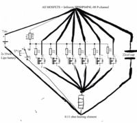
Hi there. I intend to use a 7.8v 46wh lipo battery to power a 0.12ohm heating element, I can only use p channel mosfets as the switch because of a digital read out I plan to add will act to complete an N channel circuit. I've been given a circuit to work to but to be honest I know very little about electronics. To my eyes this seems overly complicated.
Can anyone tell me if this will even work, and at that would it be efficient?

Please excuse the rough diagram, I found drawing this on a mobile phone to be quite difficult!

Any help here would be genuinely appreciated.
Mike

 
Last edited by a moderator:

the circuit topology of having many p-mosfets in parallel is to share the current of the heater.

But , the power consumed is approx 430W . Will the battery (7.6v,35Wh) is capable of supplying it ?.
 

...and do you really need to be able to switch 480 Amps (MOSFET rating) when the load is ~70 Amps.
Expect a battery life of about 2 minutes if it doesn't melt down first.

Brian
 

The battery spec on the diagram is outdated, sorry, my bad. It'll be powered by a 7.8v 2S lipo silicone-graphene 46wh battery first off, allowing provision for a more powerful cell later on. The circuit is only live for a few seconds at a time every few seconds, so the overall battery life will be short but will fulfil it's time requirements. It doesn't need to be running a .12ohm element either to be honest, as I'll be making it myself I can vary that somewhat, it just falls as easy to do @ .12 and gives me a baseline number to work to.

I'm sorry my description is so vague compared to the diagram, I needed starting point math as a parameter to work from. All my variables will ascend from that point if that makes any sence..

So.. you guys see this as a viable circuit, all be it over engineered? There's nothing dangerous (with the exception of the current battery's output limit)?
 

Thanks for your help! Owe you one :)

(I'd also like to apologise for the warning I received, I couldn't see another way to attach an image using mobile version. Sorry.)
 

Can I ask if someone could show me this circuit diagram with N channel mosfet instead of P please. I'm not skilled enough to design it myself :/

Ive had a thought that If I do not use the monitoring device I was planning I could use an N channel switch and monitor the thermal output externally instead of the power output internally..

The circuit will need to have the lowest possible internal resistance and be capible of switching similar loads as the P channel I added before.

Thanks in advance. Mike.
 

Suggest to flip the schematic top-down, replace P by NMOS and change + to - and vice versa. Skilled enough to do so?
 

I'll sure give it a go, thanks FvM.

I was really hoping the P to N change was as simple as that but I had no clue if the resistor or capacitors value would need to change, following a diagram is about where my skill ends unfortunately.

I'll not hold it against anyone if they drew it out for me ;)
 

NMOS solution can use fewer transistors due to considerably lower Rdson.

A possible problem of your circuit is inductive overvoltage during switch-off. Circuit inductance should be estimated and stored energy checked against transistor avalanche rating. Consider that the mechanical switch causes contact bounce with multiple on/off events.
 

Followed the first bit ok.. but the last paragraph went somewhat over my head I must confess.

There will be multiple on off events for sure, if there's a problem it could be catastrophic given the load I'm considering.

The avalanche is where the mech switch becomes redundant and current flows through the mosfet right? That's bad.. and so is my math :/ (largely why I **** at circuit design) I can't calculate stored energy and even if i could I don't know if I should check it against one mosfet's avelanche or the accumulated total of all of them.

I'll be physically holding this device, if there's a safer way to make circuit or an easy way of checking the one I have I'd be very grateful if someone could share it with me.
 

Status
Not open for further replies.

Part and Inventory Search

Welcome to EDABoard.com

Sponsor

Back
Top