Continue to Site

Welcome to EDAboard.com

Welcome to our site! EDAboard.com is an international Electronics Discussion Forum focused on EDA software, circuits, schematics, books, theory, papers, asic, pld, 8051, DSP, Network, RF, Analog Design, PCB, Service Manuals... and a whole lot more! To participate you need to register. Registration is free. Click here to register now.

[SOLVED] Will this circuit work?

Status
Not open for further replies.

Fworg64

Junior Member level 2
Joined
Mar 23, 2011
Messages
21
Helped
2
Reputation
4
Reaction score
2
Trophy points
1,283
Location
North Dakota
Activity points
1,441
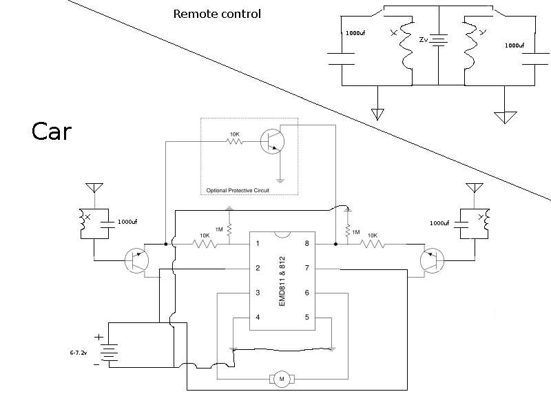
Mainly concerned about the radio-ish stuff on it 'cause i followed the data sheet of the IC pretty close.


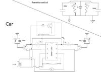
Also, what voltage should i run the remote control at?
And, any particular level of inductance for the inductors?
And, instead of the "optional protective circuit" do i still need to bridge those two points?

Thanks for any help!
 

Absolutely no chance!

To get any sort of reasonable Q factor the inductors would have to be several Henries. Think in terms of several thousand turns of wire each and a maximum radio range of a few inches at best.
It would be more productive to use the remote to push the motor around!

Brian.
 
Thanks for the reply, well the diagram didn't literally mean 3 turns, but as it turns out a bought a package of toroid coils thinking they would work. Thankfully I haven't opened the yet so i can return them.

Would changing the value of the capacitor be of any use (so i can use a smaller value inductor)?

But other then that all the parts are in the correct place, right?
 

That's not what I meant was wrong. The IC is basically two switches, one at each side of the motor, turning one on makes the motor rotate one direction, turning the other on makes it rotate the other way. The protection circuit is there if needed to ensure it isn't possible to turn both switches on at the same time as this would damage the IC.

Your problem is where you get the signal from to control the IC. You must use a radio transmitter and receiver but yur diagram shows neither. Your transmitter would produce just a few cycles of signal at an extremely low frequency and even then only if you used a huge inductor for the coil. Your receiver has the same problem and it also has no way to distinguish beteen forward and reverse control signals. Even to get a reasonable few cycles of RF an assuming an inductor of say 2 Henries, the frequency would be (f = 1 / 2* pi * sqr(L * C)) or with real figures 1/(6.28 * sqrt(2 * 1000^10-6)) = 3.56Hz. So the transmit and receive antennas would ideally be quarter wavelength long which is about 13,170 miles long each. This is probably not what you wanted!

What you need is a proper RF data transmitter and receiver. Encode the data at the transmitter so it carries information on which way the motor is to turn and decode it at the receiver into one of two control signals, connect one control signal to one input of the IC and the other control signal to the other input. It is a MUCH more practical solution and saves enough antenna wire to wrap around the Earth twice as well!

Brian.
 
Thank you once again for teh help,
After applying some math (during summer :| ) I indeed would want a smaller value capacitor, such as 15uf (Or Something) to solve the antenne problem, and similarly, a small value inductor.

But does a higer frequency mean less range? (how can i get maximum range?)

As for the encoding of data i figured i would use frequency modulation, implemented by just having two recievers tuned to two different frequencys, I thought that would be simpler than implementing a decoder.
 

take a look at this: **broken link removed**

they use HT12E for encoding and HT12D for decoding to send the data trough the rf modules. you can find many other tutorials/examples of this on web, right now i just remember this one.

Iuri~
 
The links Iuri gives will give you the right idea and it would not only be far less expensive to build but far simpler and more reliable. Even if you dropped the capacitor to 15uF they would still be too big by a factor of 1,000 and if you used two frequencies as you suggested, consider what would happen if something else transmitted on the second frequency, it would probably kill the IC instantly.

Aim for a license free frequency areoud 433.92 MHz where tha antennas are short and use an encoder and decoder, it is a cheap and very reliable way of doing what you want.

Brian.
 

Thanks Iuri for the links, i will probably ending up going that route, however i was hoping in doing this in the most gheto may possible :p , but that will probably be the way to go since i plan on expanding the rc cars fuctions, things such as... turning. Thank you all for the help!
 

Status
Not open for further replies.

Similar threads

Part and Inventory Search

Welcome to EDABoard.com

Sponsor

Back
Top