Continue to Site

Welcome to EDAboard.com

Welcome to our site! EDAboard.com is an international Electronics Discussion Forum focused on EDA software, circuits, schematics, books, theory, papers, asic, pld, 8051, DSP, Network, RF, Analog Design, PCB, Service Manuals... and a whole lot more! To participate you need to register. Registration is free. Click here to register now.

wideband circuit matching technique

Status
Not open for further replies.

mkrupi10

Newbie level 6
Joined
Dec 30, 2010
Messages
14
Helped
0
Reputation
0
Reaction score
1
Trophy points
1,283
Activity points
1,425
Hi!
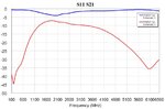
I have a circuit with S11 parameters and I want to match it to 50 ohm beetween 400 and 2500MHz. Default input reflections (S11) are not even close to 50.
Becouse I need wideband I did some tests with optimization (fminsearch) and I got some reasonable results as long as S11 was static(one frequency S11).
But, ofcourse real world S11 are not static at all... With real S11 no usable matching circuit was found yet. So far only L and C is used.
What are best technique for wideband matching, like that?
 

In the general case, it may be impossible. Consider e.g. a small band antenna with respective resonant input impedance characteristic. It's not possible to increase the bandwidth by means of a lossless passive network.
Wide band matching is often possible for circuits with continuous impedance slope, e.g. transistor amplifiers.
 

    mkrupi10

    Points: 2
    Helpful Answer Positive Rating
It's not possible to match an Impedance over a wide-band with a single matching circuit.
You will use cascaded multiple matching circuits so that each one will match the impedance to fraction of whole bandwidth.
But it's really difficult problem.
If S11 belongs to a transistor or wide-band amplifier, a small amount of series/parallel feedback will help you much.
 

What is your circuit having the given S11? A schematic would be helpful.
If there are no resonances inside of the 400MHz-2500MHz, may be possible to get a decent wideband matching, at the expense of losing some gain (and noise figure) if is about an LNA input.
 

S11 input.PNG

Here is the S11 ploted on a smith chart. It starts at lower side(100MHz) and ends on uper(6.5GHz). It's differential input (therefore two lines) to IC where first stage probably is LNA.
 

No useful S11 representation without some frequency points. You should also perform line extension to an appropriate reference plane, e.g. chip pin.
 

Code:
! Frequency    |S11|    <S11   |S21|    <S21   |S12|    <S12   |S22|    <S22
# GHz S MA R 50
0.1            0.9460 -15.500  0.0111  11.542  0.0108  3.6538  0.9467 -15.727
0.2            0.9334 -30.377  0.0062  85.695  0.0038  107.79  0.9330 -30.275
0.3            0.9290 -44.049  0.0132  92.938  0.0120  105.32  0.9348 -43.671
0.4            0.9284 -57.877  0.0182  101.09  0.0182  112.34  0.9326 -57.332
0.5            0.9262 -71.317  0.0221  116.35  0.0228  126.59  0.9350 -70.290
0.6            0.9242 -83.928  0.0333  136.21  0.0356  141.90  0.9329 -82.786
0.7            0.9193 -96.282  0.0564  144.25  0.0604  146.49  0.9261 -95.219
0.8            0.9079 -108.62  0.0900  141.09  0.0954  142.44  0.9177 -107.00
0.9            0.8964 -120.81  0.1316  133.22  0.1363  134.50  0.9042 -118.56
1              0.8682 -132.99  0.1755  123.49  0.1818  124.96  0.8812 -130.21
1.1            0.8424 -145.34  0.2234  114.03  0.2304  114.88  0.8521 -141.79
1.2            0.8101 -157.21  0.2717  103.76  0.2793  104.73  0.8234 -152.75
1.3            0.7739 -169.76  0.3174  92.695  0.3273  93.646  0.7902 -164.34
1.4            0.7477  178.41  0.3588  82.307  0.3670  82.932  0.7592 -175.96
1.5            0.7148  166.91  0.3922  72.153  0.4023  72.712  0.7290  173.05
1.6            0.6936  155.14  0.4173  62.268  0.4276  62.414  0.7086  161.67
1.7            0.6736  144.29  0.4345  52.587  0.4444  52.771  0.6886  152.13
1.8            0.6543  134.75  0.4433  43.566  0.4533  43.733  0.6754  142.62
1.9            0.6341  125.76  0.4439  34.941  0.4516  34.988  0.6694  134.43
2              0.6271  119.37  0.4297  27.065  0.4373  27.259  0.6737  127.65
2.1            0.6328  114.73  0.4098  21.574  0.4161  21.517  0.6876  121.18
2.2            0.6660  109.14  0.3994  17.766  0.4059  17.873  0.7050  114.08
2.3            0.6989  102.87  0.3971  13.446  0.4053  13.701  0.7216  108.07
2.4            0.7123  97.473  0.3946  8.3329  0.4014  8.2083  0.7326  102.96
2.5            0.7135  92.651  0.3783  2.7508  0.3844  2.6935  0.7473  98.337
2.6            0.7323  90.022  0.3589 -0.1529  0.3638 -0.1570  0.7646  95.213
2.7            0.7629  86.999  0.3443 -2.2416  0.3530 -2.3600  0.7886  91.073
2.8            0.7903  83.364  0.3410 -4.1502  0.3474 -4.5376  0.7985  87.088
2.9            0.8064  79.711  0.3357 -6.8711  0.3438 -7.2399  0.8150  83.277
3              0.8229  76.283  0.3337 -9.8672  0.3381 -10.019  0.8223  79.582
3.1            0.8334  72.745  0.3287 -12.966  0.3325 -13.201  0.8269  75.972
3.2            0.8422  69.582  0.3233 -16.053  0.3254 -16.156  0.8349  72.741
3.3            0.8470  66.365  0.3174 -19.496  0.3192 -19.684  0.8373  68.807
3.4            0.8485  62.932  0.3099 -22.629  0.3140 -22.928  0.8390  64.664
3.5            0.8544  59.345  0.3045 -26.057  0.3046 -26.526  0.8405  60.961
3.6            0.8562  55.620  0.2961 -29.582  0.2953 -30.606  0.8402  56.551
3.7            0.8554  51.873  0.2845 -33.538  0.2864 -33.724  0.8393  51.930
3.8            0.8569  47.732  0.2741 -37.554  0.2731 -37.790  0.8402  47.343
3.9            0.8569  43.372  0.2606 -41.803  0.2603 -41.947  0.8398  42.511
4              0.8582  38.759  0.2474 -45.831  0.2464 -46.362  0.8442  37.319
4.1            0.8595  33.975  0.2308 -49.762  0.2305 -50.637  0.8475  32.727
4.2            0.8626  29.142  0.2145 -53.632  0.2134 -54.078  0.8518  28.191
4.3            0.8661  24.705  0.1966 -57.402  0.1959 -57.942  0.8567  23.869
4.4            0.8718  20.194  0.1804 -60.801  0.1793 -61.104  0.8627  20.044
4.5            0.8750  16.049  0.1632 -64.204  0.1622 -64.534  0.8691  15.840
4.6            0.8868  11.714  0.1465 -67.114  0.1460 -67.405  0.8740  12.093
4.7            0.8898  8.1836  0.1314 -69.532  0.1294 -70.083  0.8875  9.3793
4.8            0.9030  5.0802  0.1163 -71.886  0.1152 -72.705  0.8924  6.5802
4.9            0.9062  2.6906  0.1025 -73.617  0.1015 -74.352  0.8973  4.1525
5              0.9152  0.3772  0.0903 -75.288  0.0890 -75.675  0.9112  2.1858
5.1            0.9238 -1.4115  0.0792 -75.844  0.0774 -76.188  0.9144  0.6122
5.2            0.9276 -2.2471  0.0691 -76.369  0.0679 -76.605  0.9221 -0.9263
5.3            0.9338 -3.2047  0.0605 -76.138  0.0589 -76.850  0.9329 -1.3607
5.4            0.9354 -3.8772  0.0518 -74.973  0.0506 -74.779  0.9328 -1.6463
5.5            0.9408 -3.7706  0.0441 -73.286  0.0436 -73.065  0.9346 -2.4276
5.6            0.9392 -4.2776  0.0369 -70.215  0.0367 -69.932  0.9325 -2.6546
5.7            0.9419 -4.2077  0.0311 -65.895  0.0310 -65.470  0.9285 -2.8155
5.8            0.9382 -3.8416  0.0258 -59.575  0.0255 -59.282  0.9255 -3.6005
5.9            0.9301 -3.4330  0.0209 -44.732  0.0211 -46.630  0.9180 -3.7716
6              0.9249 -3.4732  0.0171 -31.375  0.0182 -31.464  0.9076 -3.8446
6.1            0.9185 -3.2466  0.0166 -9.4795  0.0173 -9.9406  0.8960 -4.4441
6.2            0.9019 -2.9307  0.0186  6.2693  0.0187  7.3922  0.8819 -4.7252
6.3            0.8902 -2.9278  0.0220  19.541  0.0221  20.472  0.8660 -4.7805
6.4            0.8760 -2.4674  0.0268  29.320  0.0276  28.793  0.8454 -5.1403
6.5            0.8565 -2.4052  0.0306  36.869  0.0321  35.306  0.8256 -5.8236
 

If you want to match the differential input impedance, you should extract differential S11 from the two port measurement. Also the target impedance is probably rather 100 or 120 than 50 ohms.

In case of an LNA, I doubt that's useful to perform a wide band transformation of the high input impedance to line impedance. Instead a resistive termination would become part of the total input impedance.
 

Your circuit is not an amplifier, because have loss (see the S21 in rectangular plot), or is not working properly (bias, etc.)

See this webinar from AWR to understand how to deal with wideband impedance matching:
 

Attachments

  • sparam.jpg
    sparam.jpg
    32.2 KB · Views: 103

Each pin is 50 OHM (and it's noted in s parameters line 2( # GHz S MA R 50 )) in case of diff. input S11 is input_p and S22 is input_n. Differential impedance is therefore 100 OHM (at least it should be). If i get single ended matching circuit for 50OHM to S11, I can easly mirror it, to make it 100 OHM...
 

Your circuit is not an amplifier, because have loss (see the S21 in rectangular plot), or is not working properly (bias, etc.)

See this webinar from AWR to understand how to deal with wideband impedance matching:
It's differential input, so S11 is reflection from input_p and S22 is reflection from input_n at 50OHM, single ended. See my previous post.
Thanks for link!
 

I have maneged to get some reasonable matching circuit between 2 GHz and 2.5 GHz (S11 < -15dB) with nelder mead optimization. Now I need something similiar for 300 - 900 MHz if I split the RX to two branches. But no solution was found so far...
 

each broadband match is its own bear to slay.
what i do to start is take the measure of S11 vs frequency. then over my band of interest, i try to model that particular input impedance as a simple network of inductors/capacitors/resistors. You do not need an precise match, just some lumped circuit that kind of has an impedance like the real world circuit you measured.

You draw that circuit on a piece of paper, and stand back...look at it, and try to find a lumped element filter circuit with the same topology. then try to absorb the real world circuits impedances into the lumped theoretical filter's element values.

good luck
 

It is a huge difference matching 2-2.5 GHz relative 300-900 MHz, using passive reactive components.
2.5 GHz is 25% above 2 GHz and 900 MHz is 300% above 300 MHz. It is a factor more then 10x in tuning range. Add that actual curve is way off from matching impedance goal.
It is also a huge diffrence if matching with real and lossy components, using real values, or ideal components and any non standard value .
Auto matching for finding best values and best topology using Murata LQW15 inductors result in this impedance:
2025.png

Blue curve is vector sum of S11 and S22. Smith center is 50 Ohm.

2025rl.png

Return loss and matching network values. It is a non symmetrical network but it works just as well if ground is replaced by signal.
Orange is unmatched and yellow is after matching.

If alternatively running auto-matching for 300-900 MHz is result as expected almost without value. Depending on what parameters that is most important can it be better to not tune at all or do a resistor match.
Resulting auto-matching, componet types, values and topology automatically optimized.:
39rl.png

Blue is unmatched and Yellow matched.
As can be seen is it not at all same components values and not same optimized topology for these both frequency ranges, which makes it very complex to find design a network that reduces losses for both these frequency ranges.

I do often design embedded wideband antennas for 4G and similar. A typical such wide freq range antenna is covering 700-2700 MHz with decent efficiency. A tuning network is always needed for these small antennas and also often small ground plane but the trick is often to mis-design the antenna impedance such that both lower and higher frequencies have gain of same matching network.

When actual mesurement for a frequency range creates a complete wide circle in Smith chart will tuning at one frequency range push away corresponding frequency at opposite side of Smith chart.

It is possible to match by chopping needed frequencies in smaller bands but also that is complicated if low loss is more important then a formal impedance match. If a matching topology chain becomes long do it tends to increase resistive losses so that matching seems to be improved but added component does not reduce loss total loss.
A resistive network can even be a better choice the using reactive components if matching is improved at similar amount of loss.

A complex topology with many components in a chain is very time consuming to develop due to several real world losses, non ideal ground and if distance between first and last components have costed phase delay and stray losses must often values be fine adjusted by trial and error.

There are simple methods to develop at least chains as above, with 4 components, in a rather well predicted way but but for actual curve is it of limited value.

A bit different way to do impedance matching is to do dynamic tuning. A wide frequency range can be covered by just two dynamic tuned components. I did use it for some cellphone antennas long ago, for embedded FM antenna 88-108 MHz as well as UHF (DVB-h). By using a high-Q antenna dynamic tuned could whole FM-band be covered with an antenna just 1 MHz wide in its 3db tuning range. Actual antenna was real small, 10x4x4 mm, but did still fullfil then existing efficiency specification, MoBile Radio Access Interface specification (MBRAI).
 
Status
Not open for further replies.

Similar threads

Part and Inventory Search

Welcome to EDABoard.com

Sponsor

Back
Top