Continue to Site

Welcome to EDAboard.com

Welcome to our site! EDAboard.com is an international Electronics Discussion Forum focused on EDA software, circuits, schematics, books, theory, papers, asic, pld, 8051, DSP, Network, RF, Analog Design, PCB, Service Manuals... and a whole lot more! To participate you need to register. Registration is free. Click here to register now.

[SOLVED] why using CMOS 4069 inverter as ampilifer?

Status
Not open for further replies.

Mryemeni

Newbie level 6
Newbie level 6
Joined
Dec 4, 2013
Messages
12
Helped
0
Reputation
0
Reaction score
0
Trophy points
1
Location
YEMEN
ecammar.blogspot.com
Activity points
103
In microchip application note AN236, a 4069 inverter is used as an amplifier in the receiver, and I can't understand the reason for that.
I tryed to simulate the inverter as it shown in the datasheet with feedback resistor using LTspice but that didn't get me anywhere, can anyone help me understand the workings of such design choice.

Thanks in advance.
 

Back in the old days, before single supply op amps, 4069s were used as amplifiers more commonly than today. I like the use here because there are six inverters in one package and the cost per amplifier is probably very low. It is unfortunate if appropriate simulation models are not available. Perhaps someone else can help with the simulation issue?
 
Simulation models for digital CMOS are often behavioral and don't accurately simulate their use as linear amplifiers. There may not be any models for that. The best you could do would likely be to find some small N and P MOSFET models and adjust their parameters to match those of the 4069.
 
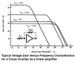
Here is a very old graph showing the typical gain and frequency response of an ordinary Cmos inverter used as an amplifier. The gain and frequency response are affected a lot by changes in the supply voltage. The distortion is very high if the output swing gets anywhere near VCC or VSS.
 

Attachments

  • Cmos amp.PNG
    Cmos amp.PNG
    18.6 KB · Views: 718
There were certain inverter P/Ns whose sole virtue was a
single stage design. Even though they are symbolized
simply, many logic inverters have multiple tapered
stages. These have a steeper transfer function and a
lot more phase-lag. The single stage inverter found a
bit of use in things like crystal oscillators and poor-boy
amplifiers.

You can distinguish the single-stage inverter types by
their "softer" transfer function, which does not rail the
output until you get to within VT of the rail at the input.

The Intersil CD4069 datasheet's application figures are
exclusively about these oddball applications. The 4009
is a more traditional multistage inverter hex.

www.intersil.com/content/dam/Intersil/documents/fn33/fn3321.pdf‎
 
In microchip application note AN236, a 4069 inverter is used as an amplifier in the receiver, and I can't understand the reason for that.
I tryed to simulate the inverter as it shown in the datasheet with feedback resistor using LTspice but that didn't get me anywhere, can anyone help me understand the workings of such design choice.

I`ve got the impression that you were asking WHY such a CMOS inverter could be used as a linear amplifier. And I am not sure if the answers up to now gave enough information about THIS question.
Therefore, my attempt to answer:

Because of its symmetric construction the CMOS inverter has an interesting property: When operated with a voltage Vdd the output will be approximately at Vdd/2 if the input at the gate nodes is also approx. Vdd/2.
More than that there is no "steep" transition between both extreme output voltages (Vdd resp. zero) but a relatively smooth transition.
Therefore, around this midpoint at Vdd/2 linear amplification is possible - and it is very easy to bias the device at this operating point using a feedback resistor between output and the common gate node (no dc current through this resistor, thus Vout,dc=Vin,dc=Vdd/2.
The input signal has to be applied using a coupling capacitor.
As a modification of this circuit (stabilization of the gain value) feedback can be applied by adding a resistor in series with the capacitor.
 
The other reason it may not simulate is that only the CD4069UB can be used in linear mode. The 'U' means Unbuffered. Normal 4069 devices only work at standard logic levels.

Brian.
 
The other reason it may not simulate is that only the CD4069UB can be used in linear mode. The 'U' means Unbuffered. Normal 4069 devices only work at standard logic levels.
The CD4069 is and was made ONLY as a UB (unbuffered) device. All the other CD4xxx devices are now B (buffered) devices. But the CD4069UB still has the same output drive current as CD4xxxB devices.
 
Thanks guys for all the information you are all awesome!
From what I understand now is that the CMOS inverter has some linear amplification characteristic when configured with a feedback resistor, the desginer from microchip used this characteristic and placed a parallel tuned circuit as to control the gain and amplify the 120khz signal alone.

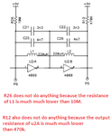
What I don't understand is how to choose the value of the resistance in the feedback?, and why the tuned amplifier is biased and the untuned is not? as seen in the image attached.

Another question, is it better to replace the inverter with opamp? if so then what opamp can replace the inverter?

Thanks in advance.

CMOS inverter.png
 
Last edited:

Your attachment does not work.

The schematic at Microchip shows no input resistor for the CD4069 inverting amplifiers so the feedback resistor value calculation cannot be made. Maybe they simply built the circuit and tried various resistor values until it worked the way they wanted.
 
The "feedback" resistor may just be for auto-biasing
the inverter to the linear (OUT=IN) point, and the
input C-R time constant is a high pass filter that you
have to match to the signal band of interest. An R-R
network would be a DC amplifier, but about a common
mode (or + input) reference point that is virtual and
somewhat unknown.
 
Of course, it is the only task of the feedback resistor to bias the inverter a the optimim operating point (Vdd/2).
Normally, it is selected with a high value because nobody likes a voltage amplifier with a low input resistor.
It cannot be calculated - unless you have a fixed coupling capacitor and a certain requirement for the high-pass cut-off frequency (as indicated already by dick_freebird.)
However, be careful - in case you want to fix the gain a a certain value using a series resistor that allows signal feedback (as mentioned in my former post) both resistor values mainly determine the overall gain acccording to the classical feedback formula.
 
Thanks guys :smile:
I reuploaded the image in my last comment.

I still did not fully understood the operation of the inverter as an amplifier :-( because there is no equation that give the gain.
the parallel tuned circuit is configured to be at resonance at the 120khz frequency and hence a maximum impedance, I guess the inverter at that moment will start to operate as an amplifier, right?
 
Last edited:

In the schematic you show, there is no explicit DC gain
control. Your AC gain is subject to the division of the
100pF input (less stray losses in the input protection)
by the feedback 10pF at high frequencies, rolled off
below (I'd say) 7-8kHz where the resistor feedback /
input capacitor 1/(2*pi*RC) is. The first stage, anyway,
is sort of hand-figuring-tractable. The second has the
output impedance of the first as divisor and you don't
really know anything about that term. If you wanted
a more fixed gain I'd say to use an interstage blocking
cap again on the second "amplifier" stage to get another
fixed Cf/Ci gain, as well as removing any threshold
mismatch from the picture (may as well increase the
centering resistor value to same as first stage I guess).
Larger Ci and Cf values would help bury the IC's parasitics'
gain error "contribution", at least up to the point where
the inverter output impedance starts to be relevant.

It's liable to be a pretty harmonic-laden output.
 
I think the two "biasing" resistors are useless. See the notes on my copy.

I made a low distortion audio generator using an inverter from a CD4069 as its amplifier. The distortion is less than 1% if the p-p output swing is half the supply voltage. Of course my inverter had a fairly high value input resistor value so it had plenty of negative feedback to keep the distortion low. If fed a switched capacitor lowpass filter IC that almost completely eliminated harmonics (0.02% distortion).
 

Attachments

  • not biasing.png
    not biasing.png
    10.3 KB · Views: 331
I still did not fully understood the operation of the inverter as an amplifier :-( because there is no equation that give the gain ?
The gain of the inverter is determined by the slope of the output characteristic showing the transistion from "high" to "low".
Normally, this is an unknown value and has a rather large tolerance. However, applying negative signal feedback (as mentioned earlier) you have the possibility to select a desired gain value because negative feedback always reduces the influence of the active device (remember: Opamp`s gain is practically determined by external resistors only).

Another question, is it better to replace the inverter with opamp? if so then what opamp can replace the inverter?

The answer to this question strongy depends on the question: What is the application for your circuit and what are the operational requirements?
 
Status
Not open for further replies.

Part and Inventory Search

Welcome to EDABoard.com

Sponsor

Back
Top