Continue to Site

Welcome to EDAboard.com

Welcome to our site! EDAboard.com is an international Electronics Discussion Forum focused on EDA software, circuits, schematics, books, theory, papers, asic, pld, 8051, DSP, Network, RF, Analog Design, PCB, Service Manuals... and a whole lot more! To participate you need to register. Registration is free. Click here to register now.

Why use dual NMOS for Wall charging over-voltage protection?

Status
Not open for further replies.

tony_lth

Advanced Member level 5
Joined
Jul 28, 2010
Messages
2,086
Helped
377
Reputation
756
Reaction score
368
Trophy points
1,363
Location
Beijing
Activity points
12,623
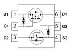
The picture is a Wall charging over-voltage protection component:
This is a typical component in mobile phone.
I have some questions for that:
(1). Why use NMOS? Just because the package of NMOS is smaller than PMOS?
(2). Why use two NMOS?
Thanks for the comments.

- - - Updated - - -

S1 is directly linked to S2.
G1 is directly linked to G2, and both are controlled by external signal.
D1 is current input, and D2 is output.
 

Attachments

  • Dual_NMOS.JPG
    Dual_NMOS.JPG
    19.9 KB · Views: 95

It's essentially an electronic switch able to disconnect both polarities. Exact function depends on the said gate control signal.

Using two FETs in an "anti-serial" configuration (source-source connected) is pretty standard for solid state relays. The component is a standard dual FET that can be used for a lot of applications, it's not specific to overvoltage protection.
 
Hi, FvM,
I have a basic question:
If S1=5V, and when Vgs=2.5V, the switch is on. So the gate voltage must be at least +7.5V, right?
If gate is 5V, when the switch is on, the Vgs=0V, so the switch be OFF again, and it's a dead cycle.
 

Yes. The correct Vgs value has to be applied relative to floating source node. This can bring up conflicts with maximum Vgs rating in some cases, thus a Vgs limiting Z-diode may be useful when dealing with higher switched voltages. If fast switching isn't an issue, the gate voltage can be supplied by a kind of ground referenced current source.
 
Hi, FvM,
thank you.
But in one reference schematic from QualComm, the P-MOS uses for battery switch and N-MOS for USB (i.e. Wall charging) switch.
Is there any reason for choosing N-MOS and P-MOS?
 

Is there any reason for choosing N-MOS and P-MOS?
Yes, if it fits the intended switching operation. Using single polarity MOSFET involves that one current direction can't be interrupted. That's O.K. in some cases. You have been initially asking about overvoltage protection for external voltage input. If you want reversal protection at the same time, you'll need a bipolar switch, otherwise an unipolar one is sufficient.
 
Status
Not open for further replies.

Part and Inventory Search

Welcome to EDABoard.com

Sponsor

Back
Top