Continue to Site

Welcome to EDAboard.com

Welcome to our site! EDAboard.com is an international Electronics Discussion Forum focused on EDA software, circuits, schematics, books, theory, papers, asic, pld, 8051, DSP, Network, RF, Analog Design, PCB, Service Manuals... and a whole lot more! To participate you need to register. Registration is free. Click here to register now.

Why two CAN channels are connected to each other?

Status
Not open for further replies.

jani12

Advanced Member level 4
Joined
Oct 30, 2014
Messages
108
Helped
0
Reputation
0
Reaction score
1
Trophy points
1,298
Activity points
2,536
Please consider steering electronic control unit (ECU). It has 6-pin CAN connector.
CAN L pin is connected to another CAN L pin in this 6-pin connector.
CAN H pin is connected to another CAN H pin in this 6-pin connector.

What are the reasons for above connections?
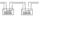
 

Its a data communications line using the CAN protocol. The H & L denotes the positive and negative bus lines. CAN uses a bus topology where the data is broadcast to all units on the bus so all units are connected in parallel on the bus.
 

@scopeprobe, your statements are correct. I'm aware of them but my question is why two CAN channels are connected to each other in a ECU CAN Connector?
 

@scopeprobe, your statements are correct. I'm aware of them but my question is why two CAN channels are connected to each other in a ECU CAN Connector?
Not sure if i'm answering the question here but the system is often constructed as a daisy chain so the Bus will enter the unit on one connector and loop straight over to the other connector to pass the data back out to the next piece of equipment in the system. It keeps the harnesses simple.
 

Not sure if i'm answering the question here but the system is often constructed as a daisy chain so the Bus will enter the unit on one connector and loop straight over to the other connector to pass the data back out to the next piece of equipment in the system. It keeps the harnesses simple.
I cannot picture this. Could you create a diagram?
 

Bus will enter the unit on one connector and loop straight over to the other connector
My question is about the same connector. My original question states how the pins within the connector are connected to each other.
 

Hi,

what about giving more detailed informations:
What ECU are you talking about? Which connector? which pins (names)? Which car?

The more detailed your informations, the better, fatster and more precise are the answers.

Klaus
 

My question is about the same connector. My original question states how the pins within the connector are connected to each other.
My previous post is also valid within the same connector. Pins can be used to provide the looping function to continue the databus. Its easier to use 2 pins and do a loop in the tracking on the PCB than it is to do it in the wire harness with 2 wires Teed off a single pin, it makes for improved reliability and keeps the harnesses simple.
 

Attachments

  • can.png
    can.png
    22.8 KB · Views: 94
Last edited:

Status
Not open for further replies.

Part and Inventory Search

Welcome to EDABoard.com

Sponsor

Back
Top