bluetooth
Junior Member level 3
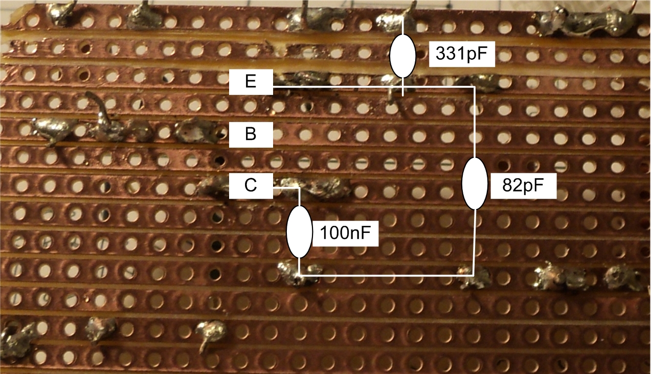
This is a Veroboard optimized oscillator. It is insensitive to parasitic inductances as the RF path around Q1 consists of only four elements. C1 and C2 can each be mounted next to the transistor. The parasitic inductance of C3 10nF doesn´t matter as the coil is in series with it. The oscillator has very high margin: It starts with 2,5V and for the Q-factor of the coil a minimum of 10 is sufficient.
---------- Post added at 10:21 ---------- Previous post was at 10:20 ----------
https://obrazki.elektroda.pl/76_1289033392.jpg
---------- Post added at 10:21 ---------- Previous post was at 10:20 ----------
https://obrazki.elektroda.pl/76_1289033392.jpg
Last edited:
")