milan.rajik
Banned
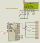
Why this Flow meter code not working ?
I am using PIC16F877A at 4 MHz external crystal. I am feeding pulses to INT0 pin. My sensor gives 330 pulses per liter of fluid and 25 liters per minute is the flow rate.
In the code if I comment out the line
then it shows some continuously incrementing data but if I uncomment then nothing is displayed on LCD except "Flow Meter".
I am using mikroC PRO PIC Compiler. What is wrong in the code ?
- - - Updated - - -
I solved the problem. Now I have a new problem. It displays 0 for liters / min and liters / hour all the time. What is the problem ?
I am using PIC16F877A at 4 MHz external crystal. I am feeding pulses to INT0 pin. My sensor gives 330 pulses per liter of fluid and 25 liters per minute is the flow rate.
In the code if I comment out the line
Code:
while(GIE_bit);I am using mikroC PRO PIC Compiler. What is wrong in the code ?
- - - Updated - - -
I solved the problem. Now I have a new problem. It displays 0 for liters / min and liters / hour all the time. What is the problem ?