Continue to Site

Welcome to EDAboard.com

Welcome to our site! EDAboard.com is an international Electronics Discussion Forum focused on EDA software, circuits, schematics, books, theory, papers, asic, pld, 8051, DSP, Network, RF, Analog Design, PCB, Service Manuals... and a whole lot more! To participate you need to register. Registration is free. Click here to register now.

Why the simulated PA current is negative?

Status
Not open for further replies.

coolsummer

Junior Member level 3
Joined
Mar 18, 2019
Messages
28
Helped
0
Reputation
0
Reaction score
0
Trophy points
1
Activity points
477
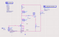
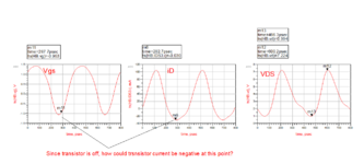
I have just simulated a simple schematic in ADS, the load ind(2nH) and cap(1pF) resonate at 2.52GHz (both of them are ideal component). The DC bias of the nmos is 0.4V, input power is 10dBm, so it is biased at class-c operation. But the simulated current of the nmos is a sine wave(even negative), other than a pulsed waveform, which is expected in class-c operation, why? Is it due to the software algorithm?(The results are the time domain waveforms after HB analysis )
 

Attachments

  • hb.png
    hb.png
    74.7 KB · Views: 82
  • dds.png
    dds.png
    36.4 KB · Views: 84

Sine waveform is in fact the expected waveform, you can review in text books. You see negative current peak during falling drain voltage, it's discharge current of drain capacitance.
 

    coolsummer

    Points: 2
    Helpful Answer Positive Rating
Status
Not open for further replies.

Part and Inventory Search

Welcome to EDABoard.com

Sponsor

Back
Top