Continue to Site

Welcome to EDAboard.com

Welcome to our site! EDAboard.com is an international Electronics Discussion Forum focused on EDA software, circuits, schematics, books, theory, papers, asic, pld, 8051, DSP, Network, RF, Analog Design, PCB, Service Manuals... and a whole lot more! To participate you need to register. Registration is free. Click here to register now.

Why the impedance is different?

Status
Not open for further replies.

TerryADS

Full Member level 2
Joined
Oct 31, 2008
Messages
133
Helped
2
Reputation
4
Reaction score
2
Trophy points
1,298
Location
USA
Activity points
2,066
Dear friends,
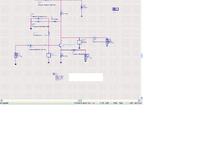
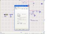
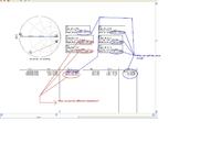
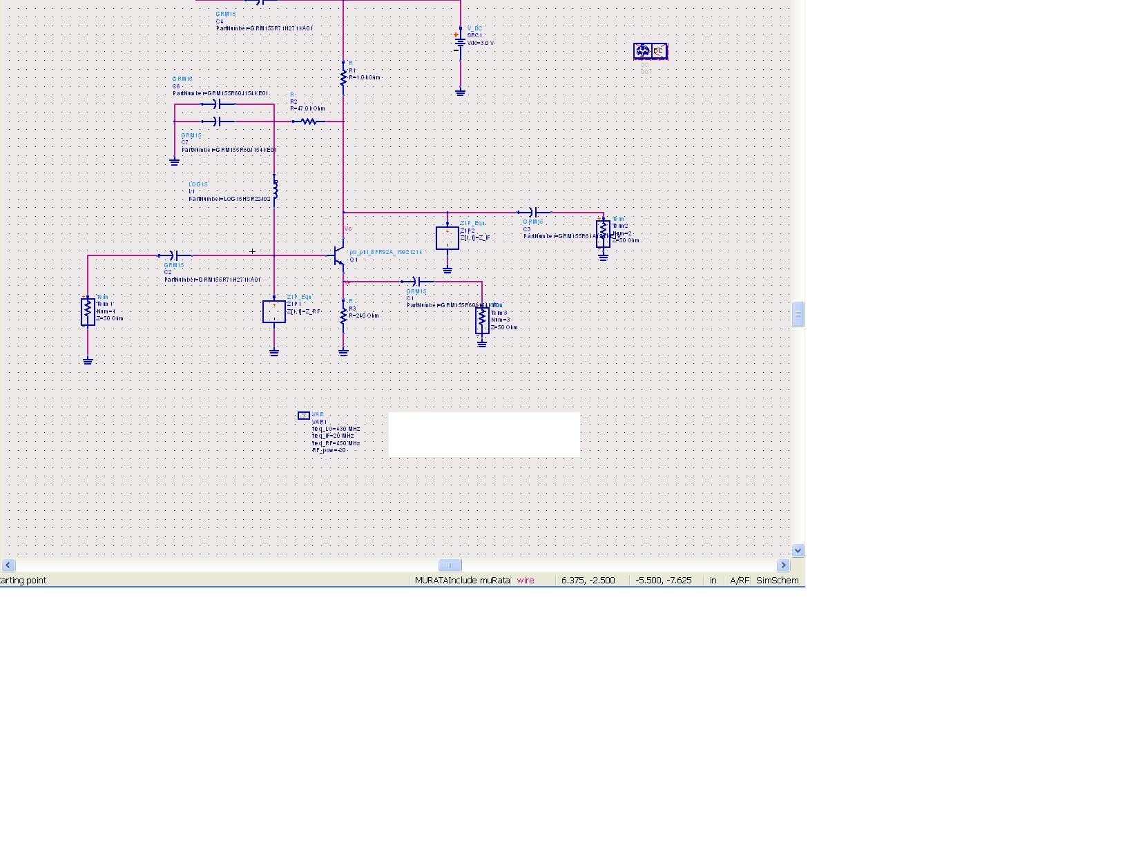
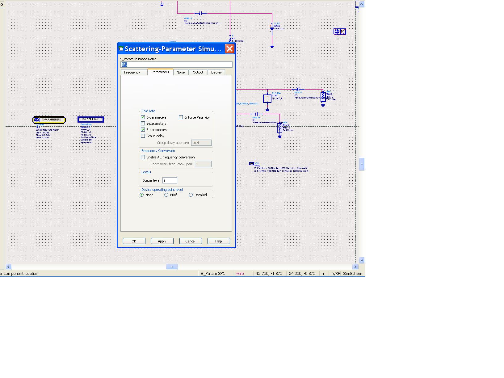
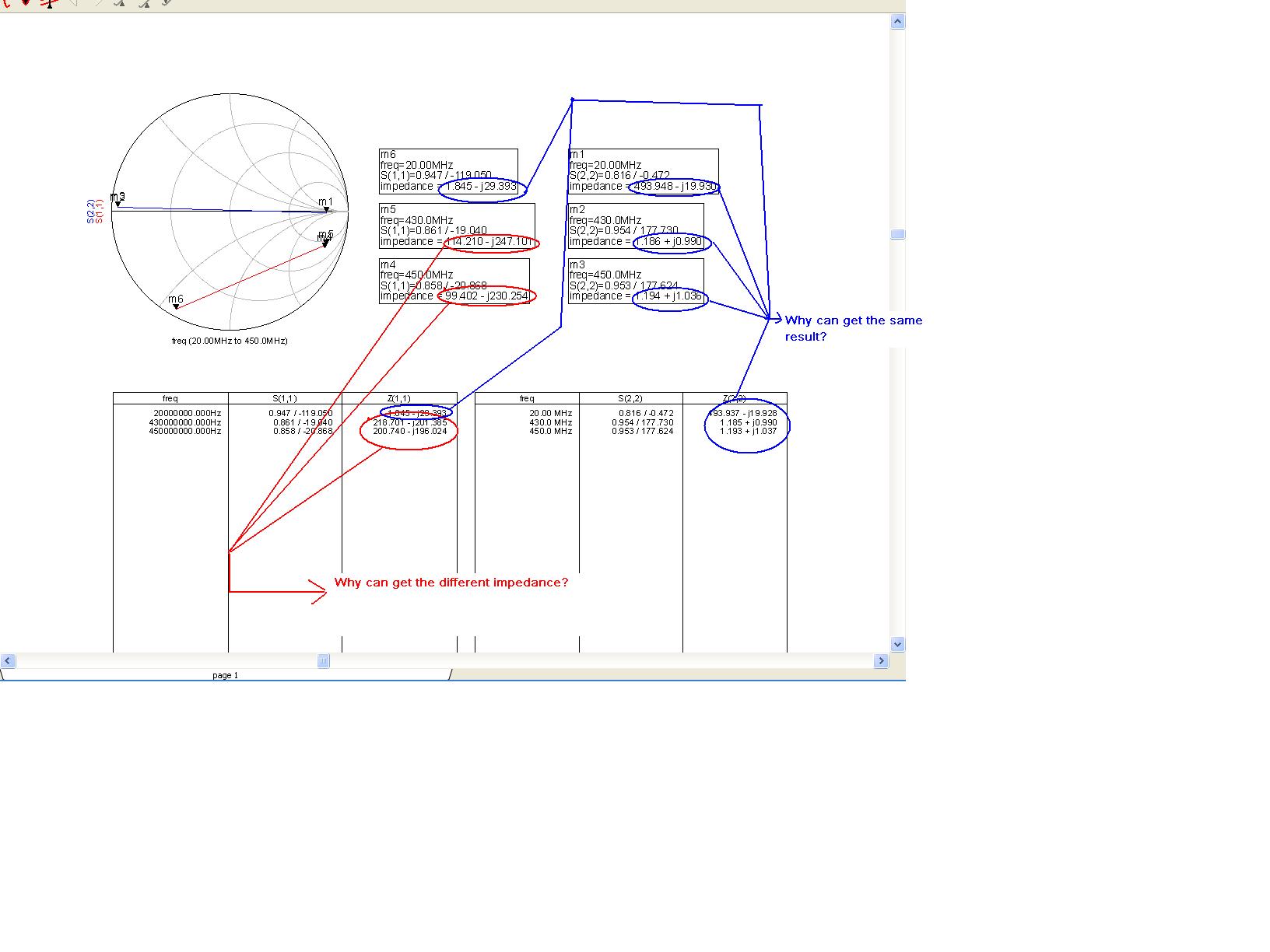
I simulated BJT mixer with ADS.when i want to match input port,i found some strange things that get the different impedance at input port between z parameter and s parameter,but output terminal can got result.
Would Any friend kindly tell me the root cause?
Thanks,


this is strange ,
could u upload ur project , so we can check it

Khouly
 

    TerryADS

    Points: 2
    Helpful Answer Positive Rating
Thanks for reply.Attached my document as bellow
 

Z Parameters are Open Circuit parameters,don't confuse with S-Parameters.Because s-parameters assume that the other ports are terminated with characteristic impedance..
Henceworth, z-parameters assume that the other ports are open..
 

    TerryADS

    Points: 2
    Helpful Answer Positive Rating
yep, z and s parameters are calculated with very different boundary conditions. Also, there are some interconnects of components that are not allowed in z parameters.
 

    TerryADS

    Points: 2
    Helpful Answer Positive Rating
Thanks for all reply.which impedance i use for input match?I should select impedance that generated from S parameter,is it right?I have a qustion why the output terminal have the same result,and 20MHZ(IF) at input port also has the same result,but 430MHZ or 450MHz have different impedamce between Z parameter and S parameter?What causes this case,how to analyze?


    TerryADS

    Points: 2
    Helpful Answer Positive Rating
TerryADS said:
Thanks for all reply.which impedance i use for input match?I should select impedance that generated from S parameter,is it right?I have a qustion why the output terminal have the same result,and 20MHZ(IF) at input port also has the same result?What cause this case,how to analyze?

Your problem is to do broadband matching if you intend to use from 20MHz-450MHz frequency band.In any case, you should use Smith Chart impedance values because ADS gives you the port input impedances looking toward to the circuit.So, if conjugate matching is necessary, you should these impedances.
But in Mixers, conjugate matching for LO port does not have the priority,instead,the LO signal should have an amplitude as much as possible(not too much to break down the B-E junction :D ).Therefore conjugate matching doesn't make sense..
I couldn't understand your 2nd question..sorry..
 

    TerryADS

    Points: 2
    Helpful Answer Positive Rating
BigBoss said:
TerryADS said:
Thanks for all reply.which impedance i use for input match?I should select impedance that generated from S parameter,is it right?I have a qustion why the output terminal have the same result,and 20MHZ(IF) at input port also has the same result?What cause this case,how to analyze?

Your problem is to do broadband matching if you intend to use from 20MHz-450MHz frequency band.In any case, you should use Smith Chart impedance values because ADS gives you the port input impedances looking toward to the circuit.So, if conjugate matching is necessary, you should these impedances.
Thanks.I want to match 450Mhz at RF input port,and 20MHz at IF(output port).
But in Mixers, conjugate matching for LO port does not have the priority,instead,the LO signal should have an amplitude as much as possible(not too much to break down the B-E junction :D ).Therefore conjugate matching doesn't make sense..
It is useful,thanks!
I couldn't understand your 2nd question..sorry..
Maybe i did not express it clearly.As above,i do S parameter simulation,and select the impedance to match to 50R at RF input port and IF port.I use Z paramter and S parameter to generate impedance,i found some different cases as my first post,i
do not know why it is different in 430MHz and 450MHz,but same in 20MHz at RF input port.


Added after 12 minutes:

mauroferrari_ said:
You should use a function in ads that i dont remember that calculate and give you the "conjugate matching impedance" simply after the S-parameter simulation.

When you have this conjugate matching impedance you have to sintetize it for example with my tool:
https://www.uwaverf.altervista.org/index.php?option=com_content&view=article&id=50&Itemid=54#match
It is very useful tool,thanks!
 

Status
Not open for further replies.

Part and Inventory Search

Welcome to EDABoard.com

Sponsor

Back
Top