Continue to Site

Welcome to EDAboard.com

Welcome to our site! EDAboard.com is an international Electronics Discussion Forum focused on EDA software, circuits, schematics, books, theory, papers, asic, pld, 8051, DSP, Network, RF, Analog Design, PCB, Service Manuals... and a whole lot more! To participate you need to register. Registration is free. Click here to register now.

Why Resonance Frequency of Frequency Selective Surface Change with Incidence Angle

Status
Not open for further replies.

trstlm

Member level 2
Joined
Jan 28, 2010
Messages
48
Helped
8
Reputation
16
Reaction score
7
Trophy points
1,288
Activity points
1,539
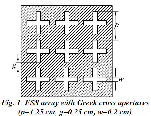
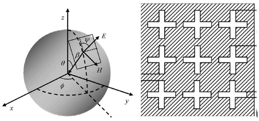
For a given dimension of element (patch or aperture type) in Frequency of Frequency Selective (FSS), the resonance frequency (Fr) change with Incidence Angle and polarization.
(Example: Let us take a dipole cross type aperture array. The length of dipole is 1 centimeter. Fr is 15 GHz for incidence angle 0 Degree. But it shifts down to 13 GHz when the incidence angle increase to 80 Degree).
Please help me to know the reason.
 

The simplest qualitative explanation is that the elements appear to be of different size to a wave coming in at an angle. Different size elements will resonate at different frequencies.

A more rigorous explanation depends on what type of frequency selective surface you are working with and what kind of physics it is employing to produce frequency selectivity. Some when coming in at an angle with shift the resonant frequency higher in frequency, while others it will shift lower in frequency.

Hope this helps!
 
  • Like
Reactions: trstlm

    trstlm

    Points: 2
    Helpful Answer Positive Rating
Thanks a lot "rrumpf".
Please find the attached FSS array. Its Greek Cross Dipole Aperture Array designed for Band Pass response at 15 GHz. Consider vertical polarized wave strike the FSS at different incidence angles (0 t0 60 degree). For all the above incidence angles, the Electric field is always parallel to a dipole. Kindly help to understand how the length appears to change with varying incidence angle.
2024740100_1400818035.png
 

By vertical, I am imagining the field polarized perpendicular to the plane of the FSS, not parallel. Anyway, the angle of incidence thing also has do to with the phase of the wave across the element. At large angles of incidence, this phase can vary more quickly and excite currents on the elements differently. This happens regardless of polarization.

If you are looking for less sensitivity to angle of incidence, experiment with hexagonal arrays and elements that are as small relative to the wavelength as possible. You can also incorporate high-k dielectrics along with some other tricks.
 
  • Like
Reactions: trstlm

    trstlm

    Points: 2
    Helpful Answer Positive Rating
Dear rrumpf! Your posts / replies on this forum on FSS are very useful. Kindly keep helping the FSS community. Still i have basic doubts on FSS, but i wont disturb you continuously.
 

No worries. In the meantime, you may find some of this material useful...

**broken link removed**
 

Sorry. One more question. Please help to understand TE/TM. Also correct if i am wrong in the following statements.

Assume FSS screen is placed in 'YZ' plane. [polarization angle-Sci;Azimuth incidence angle-phi;elevation inc angle-theta]
(i) 'XZ' is incidence plane. Whether it should be the plane perpendicular to surface and contain varying phi & theta. For TE, Magnetic field is parallel to XZ and E field should perpendicular to XZ. During practical measurements, if wave is transmitted by horn, then how do we know the plane of incidence also the TE/TM.
(ii) While finding the Tx/Rx response of FSS screen, why TE and TM polarization's only considered in CST/HFSS. CST don't have option to vary the polarization angle, but have option to change the number of modes in TE/TM. Is the Floquet support TE/TM polarization like waveguide.
(iii)Whether HFSS have the option to vary polarization angle.
(iii)Is varying the modes in TE(or)TM is relevant to varying the polarization.
(iv)The problem i'm facing is i want to compare the measurement result with simulation. Where in measurements i can change the polarization angles (30,60), but in FSS unit cell simulation i cant.

Thanks.
 
Last edited:

(i) Your sense of TE and TM seems correct to me. In an experiment, the angle of incidence is set by the orientation of the horn relative to the FSS. In many anechoic chambers, there is a rotatable platform, sometimes robotic, that slowly turns the FSS as the frequency response is being measured for each angle. Usually standard-gain horn antennas are used that transmit a mostly linearly polarized beam. To change from TE to TM, simply rotate the antenna 90 degrees. Be sure your illluminating horn is sufficiently far from the FSS to get a nearly plane wave wavefront at the FSS.

(ii) I don't know CST, but I still think I can answer this question. CST probably only provides options for TE and TM because you can make any polarization from just a combination of these two. For example, if you want a linearly polarized beam at a 45 degree angle between the TE and TM, you would simply set the amplitude of both TE and TM to 1/sqrt(2). If you want a circularly polarized beam, you would do the same, but give the two a 90 degree phase shift between them. If you want to see a bit more on polarization, TE, and TM, see Lecture 3, Slides 9-21 here:

**broken link removed**

(iii) HFSS does have this option. I think mostly any tool will have this option, including CST. I think CST is very expensive compared to HFSS and in my experience HFSS produces results that more closely resemble what we measure in the lab. CST may be better for very large structures, but HFSS now has a time-domain solver. For periodic FSSs, it will be hard to beat HFSS.

(iii) Yes! See above.

(iv) I think you can vary the polarization angle. Check to see if you can vary the amplitudes of both TE and TM. If not, but I think you can, do it manually. Figure out the two amplitudes, simulate the TE, simulate the TM, and then add the results.
 
  • Like
Reactions: trstlm

    trstlm

    Points: 2
    Helpful Answer Positive Rating
Status
Not open for further replies.

Part and Inventory Search

Welcome to EDABoard.com

Sponsor

Back
Top