Continue to Site

Welcome to EDAboard.com

Welcome to our site! EDAboard.com is an international Electronics Discussion Forum focused on EDA software, circuits, schematics, books, theory, papers, asic, pld, 8051, DSP, Network, RF, Analog Design, PCB, Service Manuals... and a whole lot more! To participate you need to register. Registration is free. Click here to register now.

Why Photocoupler break down???Help me..

Status
Not open for further replies.

erenkcms

Junior Member level 3
Joined
Oct 31, 2006
Messages
25
Helped
2
Reputation
4
Reaction score
2
Trophy points
1,283
Location
Turkey
Activity points
1,448
Hi everybody,
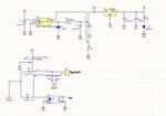
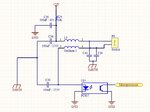
I have a problem about photocoupler. I have attached my schematic.when the P9 switch on/off, i take this changing by U15(PC817) to my microprocessor, but my problem is when P9 switch on/off more than 1 times, the U15(PC817) break down..?? when i change U15 , it works a little bit time and again break down U15..WHY? Do you have ANY idea??Please help me...!!!!
 

Attachments

  • schematic.jpg
    schematic.jpg
    101.5 KB · Views: 134
Last edited:

try to put resistor from the microprocessor side. Also the photo-diode needs about 1.2volt Vforward and 5mA maximum current. So you need a voltage divider from the switch side.
 

You need resistor on LE diode side of optocoupler, you kill LE diode with high current.

That resistor will limit current for LED and resistor value depends from optocoupler specification and what you want to do.

Resistor on transistor side can be used for pull-up/pull-down purposes, and of course to limit current in circuit if needed.
 

hi erenkcms you seem to be making a grave mistake by feeding the AC supply voltage straight to the optocoupler without a current limiting resistor.
first of all the optocoupler is rated at about 60mA maximum forward current and a maximum reverse breakdown voltage of about 5 Volts so you see that from your design that there is a flaw so all you have to do is to make use of the specs provided so that you will not end-up destroying the chip.

just place a resistor in series with the optocoupler from the AC side.... that is to say limit the current that flows through from the anode with say a 120K to 220K resistor so that the current as well as the voltage across the optocoupler will drop this will help you else you will keep on blowing it up with you current design.
 

i think you dont see my current limiter resistor which is R24=10K Ohm and this series my supply +24 and my current is 24V/10k=2.4mA..
 

What you say for flyback diodes over coils.

Put two diodes over each coil with cathode oriented to plus.

Limiting resistor for LED of optocoupler should be between coils and optocoupler - closer to optocoupler.
 
Last edited:

hmm i see, but i can not understand, why should be close? the resistor is limiting, it is no important where the resistor? am i wrong? or can you explain me why should be close?
 

L3 coil is only for filtering, you can think that P9 is only short circuit.

In that case put one diode over L3 with cathode oriented to plus, second diode forget.

- - - Updated - - -

https://en.wikipedia.org/wiki/Flyback_diode

According to Lenz's law, if the current through an inductance changes, this inductance induces a voltage so the current will go on flowing as long as there is energy in the magnetic field. If the current can only flow through the air, the voltage is therefore so high that the air conducts. That is why in mechanically-switched circuits, the near-instantaneous dissipation which occurs without a flyback diode is often observed as an arc across the opening mechanical contacts. Energy is dissipated in this arc primarily as intense heat which causes undesirable premature erosion of the contacts. Another way to dissipate energy is through electromagnetic radiation.

Similarly, for non-mechanical solid state switching (i.e., a transistor), large voltage drops across an unactivated solid state switch can destroy the component in question (either instantaneously or through accelerated wear and tear).
 

could you explain me that why we are using this diode? by the way thank you fro your support..
 

Thank you very much for your explaining,
i will try it tomorrow..i hope it works..
 

now L3 is one core and two enductance winding on it, my purpose is that for using this core, if any noise comes from P9 to my circuit (ground or +24) L3 will block it.
so i can put diode low side(close side to PC817) as cathode to plus but i can not use diode on high side (up to P9) because all noises passes from diode to +24, so if i dont use diode on it, it could be problem?
 

What noise do you have on power supply? 24V is battery or something else?

I supose you want to sense switch, in that case this noise cant be reflected to final goal. Except in case if you consider under noise some variations in voltage or high peaks.... You definitely have peak strikes on optocoupler led caused by coil without protecting flyback diode.

My opinion is that all of thise capacitors and coils are unnecessary. Better explain and describe noise, maybe we can make some solution. Maybe is better to make first some good voltage stabilisation with filtering, and then you can use what you want, from uC to leds and other things. :wink:
 
Last edited:

Yes you are right i want to sense switch, this switch cable is too long (more than 15 meter) and this switch cable is parallel to 650A load cable ( there are very much noises)..so if some noises comes from this cable to my PCB , my microprocessor should be locked. and when i design this PCB i thought that if i use here bobin, high frequencies noises will be blocked in bobin and my PCB will be clear...
 

650A ??? 8-O are you somewhere in some nuclear submarine? :grin:

What else do you plan or you have on PCB, is there some IC or uC ?

Maybe is better to protect device with case shielding and grounding, with designed power supply including filtering on output. Like lowering voltage from 24V to 12V and make stable filtered voltage on output for powering your PCB.
 

ehe ehe ehe :) no welding machines :) 650A DC :).
I have a PCB and there is a uc on it.
I already do that I am sending +24VDC to switch and i regulate +24 VDC to +12 VDC with LM2575-ADJ and i am regulate +12V to +5V for uc with 7805..:)
I atteched it.
 

Attachments

  • schematic_2.jpg
    schematic_2.jpg
    90.6 KB · Views: 103
Last edited:

Yes you can use regulators and no problems, if you use HF currents during welding, and some problems shows with device, maybe consider shielding complete PCB, and move to another location far away from HF sources.
 

A couple of things I see here:
1) L3 will generate back EMF which will fry U15.
2) C40, C29 C39 and C30 are grounded at different potential - not referenced to U15 = ground loop

If you are concerned about noise getting into P9, I would reverse the logic on the MCU
and keep only R24, C36, P9 and U15. The R24 connected directly to U15 from the +24VDC.
P9 and C36 all connected to U15 directly.
 

Status
Not open for further replies.

Part and Inventory Search

Welcome to EDABoard.com

Sponsor

Back
Top