jayanth.devarayanadurga
Banned

- Joined
- Dec 4, 2012
- Messages
- 4,280
- Helped
- 822
- Reputation
- 1,654
- Reaction score
- 791
- Trophy points
- 1,393
- Location
- Bangalore, India
- Activity points
- 0
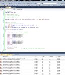
Why I am getting errors when Compiling this Code?
Atmel Studio 6.1 Code. ATMega128, 8 MHz
Project files + Proteus file attached.

Atmel Studio 6.1 Code. ATMega128, 8 MHz
Project files + Proteus file attached.
Code C - [expand]